4 Heat pump data, components
Note! Illustrations of products are not precise drawings and must only be considered as schematic images.
Differences in component parts may occur.
4.1 DHP-H, DHP-H Opti
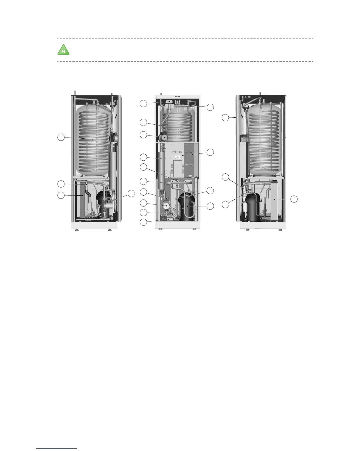
Figure 3. Components
Symbol explanation
1 Water heater, 180 litres 12 Drying filter
2 Return pipe sensor, heating system 13 Expansion valve
3 Evaporator, insulated 14 Hot water temperature sensor (displays maxi-
mum temperature)
4 Reversing valve 15 Control panel for control equipment
5 Supply line sensor 16 Electrical panel
6 Heating system circulation pump 17 Compressor
7 Auxiliary heating, immersion heater 18 Low pressure switch
8 Brine in 19 Operating pressure switch
9 Heating system supply line 20 High pressure switch
10 Brine out 21 Condenser with primary side drain
11 Circulation pump coolant system
10 – Service instructions VMGFC302
 Loading...