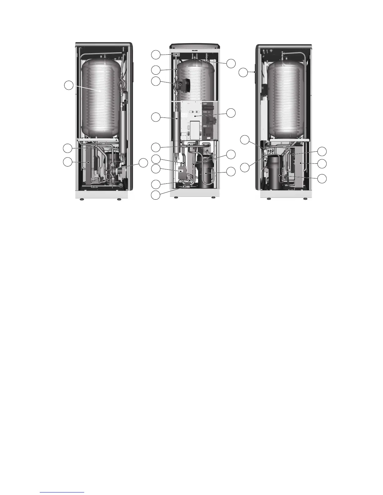
Figure 4. Components
Symbol explanation
1 Water heater, 180 litres 13 Drying filter
2 Return pipe sensor, heating system 14 Hot water temperature sensor (displays max-
imum temperature)
3 Evaporator, insulated 15 Control panel for control equipment
4 HGW shunt valve 16 Electrical panel
5 Supply pipe sensor, heating system 17 Compressor
6 Heating system circulation pump 18 Low pressure switch
7 Auxiliary heating, immersion heater 19 Operating pressure switch
8 Brine out 20 High pressure switch
9 Heating system supply line 21 Condenser with primary side drain
10 Brine in 22 De-superheater
11 Circulation pump coolant system 23 HGW sensor
12 Expansion valve
Service instructions VMGFC302 – 11
 Loading...