Close to the
evaporator
1
3
2
COM
5V+
DI2
DI1
COM
AI4
AI3
AI2
DI3
COM
D–
D+
RGND
CAN RJ
–/~
+/~
GND
Bat+
A1
A2
B1
B2
NO1
C1
NC1
COM
5V+
DI2
DI1
COM
AI4
AI3
AI2
DI3
COM
CAN RJ
–/~
+/~
GND
Bat+
A1
A2
B1
B2
NO1
C1
NC1
COM
5V+
DI2
DI1
COM
AI4
AI3
AI2
DI3
COM
D–
D+
RGND
CAN RJ
–/~
+/~
GND
Bat+
A1
A2
B1
B2
NO1
C1
NC1
COM
5V+
DI2
DI1
COM
AI4
AI3
AI2
DI3
COM
CAN RJ
–/~
+/~
GND
Bat+
A1
A2
B1
B2
NO1
C1
NC1
COM
5V+
DI2
DI1
COM
AI4
AI3
AI2
DI3
COM
D–
D+
RGND
CAN RJ
–/~
+/~
GND
Bat+
A1
A2
B1
B2
NO1
C1
NC1
COM
5V+
DI2
DI1
COM
AI4
AI3
AI2
DI3
COM
CAN RJ
–/~
+/~
GND
Bat+
A1
A2
B1
B2
NO1
C1
NC1
Danfoss
80G295.10
–/~
+/~
–/~
+/~
Superheat controller
EKE 1x - 080G5xxx
Superheat controller
EKE 1x - 080G5xxx
Superheat controller
EKE 1x - 080G5xxx
EKE EKE EKE
DKRCC.PI.RS0.C6.02 | 6
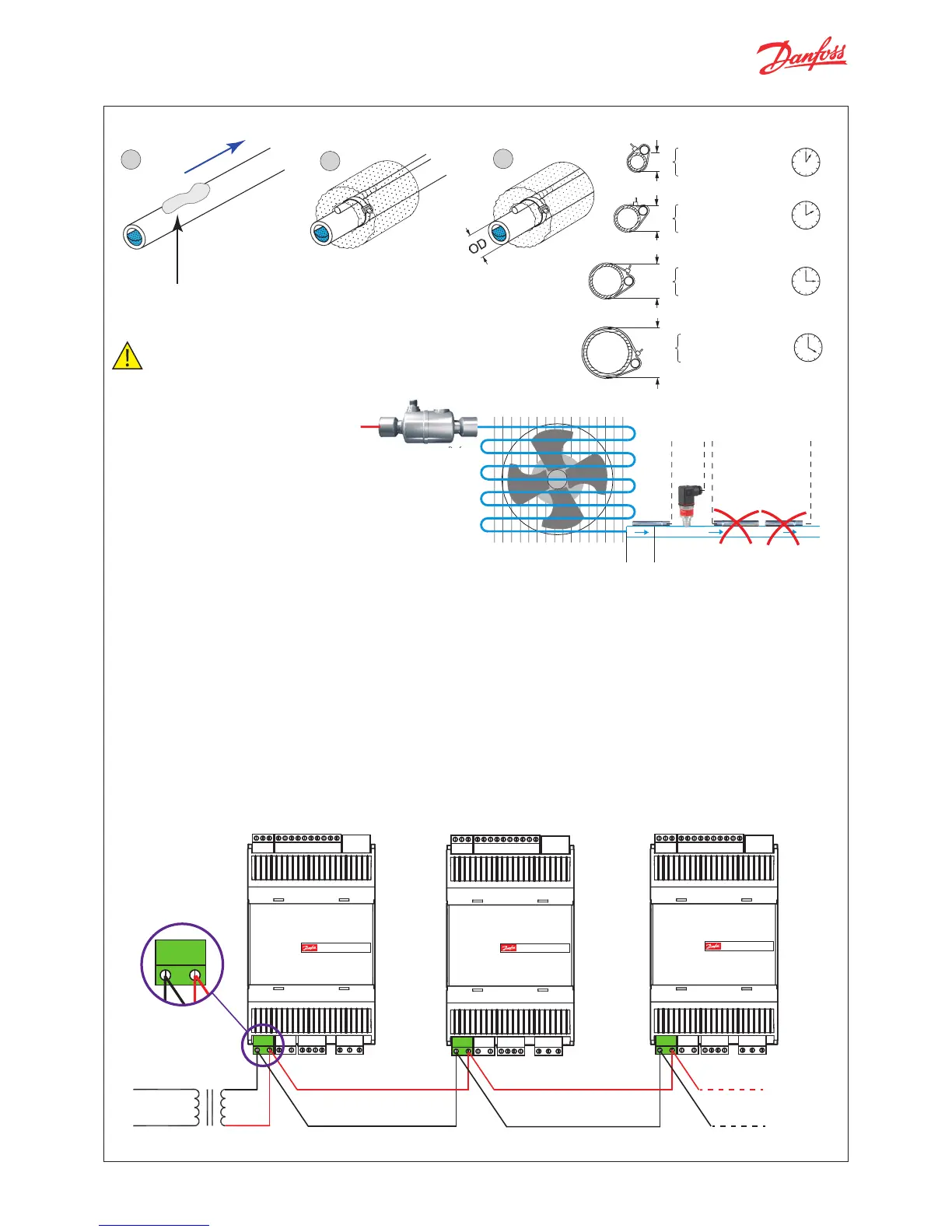
Evaporator outlet
Conductive
paste
Important Note
• Mount the sensor on a clean
paint-free surface.
• Remember to use heat
conducting paste and insulate
the sensor.
• For precise measurements,
mount the sensor max. 5 cm
from the outlet of the evaporator.
Evaporator
Sensor mounting: Temperature sensor
Pressure transmitter
• Installation of the pressure transmitter is less critical. However, the pressure transmitter should be closer to
the temperature sensor, right after the evaporator and with its head upright. It is a good practice to select
a pressure transmitter with an average load of 40 - 60% of full scale.
• 5 EKEs at maximum are allowed to share the output signal of a ratiometric pressure transmitter.
In order to get a correct acquisition on all the units all the three wires (GND, 5 V and transmitter signal
output) must be routed to every unit.
Power supply
• Power sharing is allowed in EKE controller.
• It is a good practice not to reverse the polarity of the power connection cables.
Selection of the common power supply depends on the total number of sharings and the valve in use.
Power supply
Close to the
evaporator
Superheat controller Superheat controller
Superheat controller

 Loading...