DKRCC.PI.RS0.C6.02 | 7
Connecting Modbus
• For the MODbus cable, it is best to use 24 AWG shielded twisted-pair cable with a shunt capacitance
of 16 pF/ft and 100Ω impedance.
• The controller provides an insulated RS485 communication interface which is connected to the
RS485 terminals (see connection overview).
• The max. permissible number of devices simultaneously connected to RS485 cable output is 32.
The RS485 cable is of impedance 120 Ω with maximum length of 1000 m.
• Terminal resistors 120 Ω for terminal devices are recommended at both ends.
• The EKE communication frequency (baud rate) can be one of the following: 9600, 19200 or
38400 baud, default 19200 8 E 1.
• The default unit address is 1, which can be changed using parameter “G001 Controller adr.”.
For a detailed explanation of Modbus installation and setting software parameters, see:
Data sheet for “EKE Superheat controller” and “EKD EIM Data Communication Modbus RS485 RTU”.
Modbus
D+
D-
Not in use
Gnd
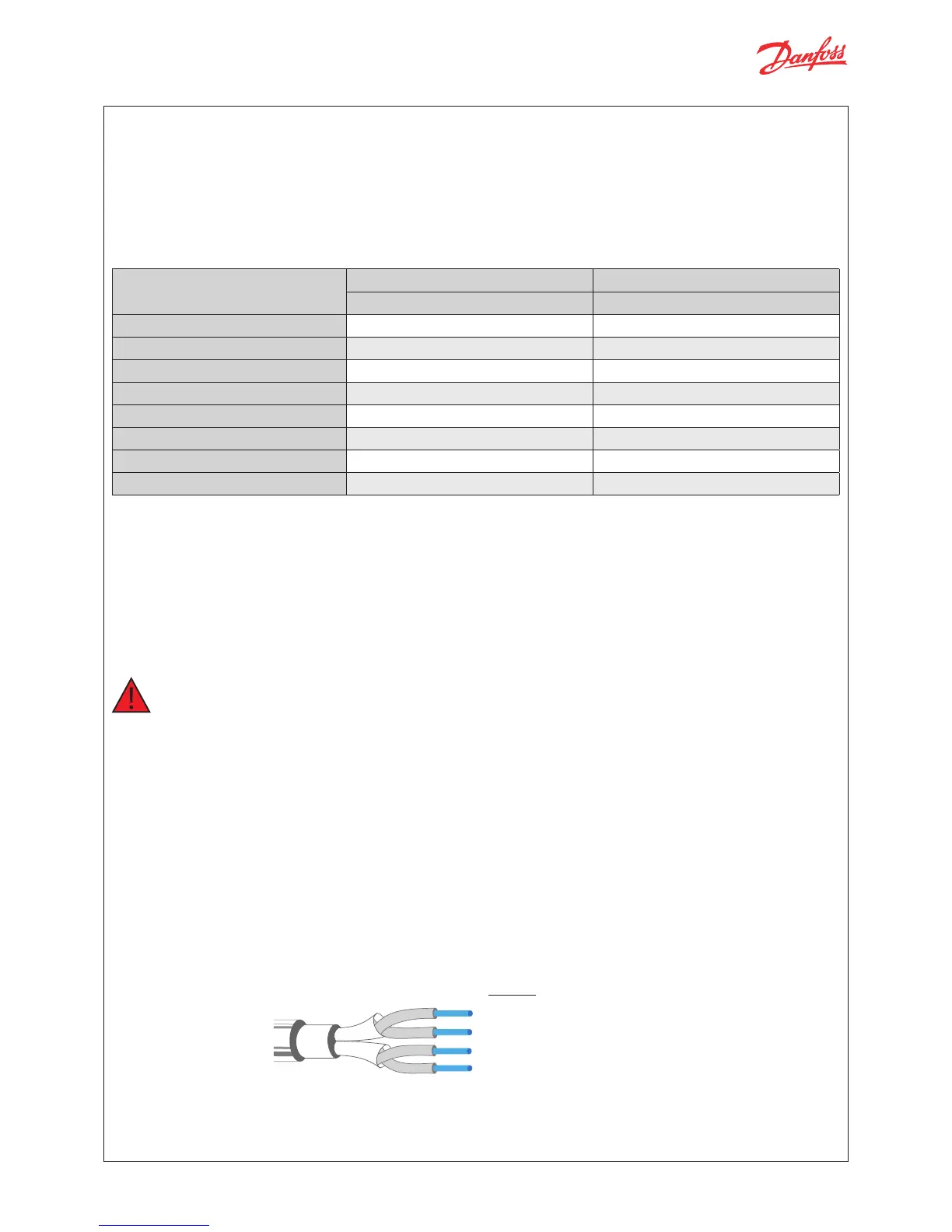
Cable length
EKE controller supports the following max. cable length.
Cable length Wire size min. / max.
[m] [m
2
]
Analog inputs (Current/Voltage) max. 10 0.14 / 1.5
Temperature sensor max. 10 *) –
Stepper valve connection max. 30 0.14 / 1.5
Power supply max. 5 0.2 / 2.5
Digital input max. 10 0.14 / 1.5
Digital output – 0.2 / 2.5
Digital MMI max. 3 over CAN RJ –
Communication bus max. 1000 0.14 / 1.5
Relay Outputs
EKE 1B has 1 relay output:
• Type SPDT relay. Digital Output can be used to connect either a solenoid valve or an alarm.
• The relays cannot be used for the direct connection of capacitive loads such as LEDs and ON/OFF control of
EC motors. All loads with a switch-mode power supply must be connected with a suitable contactor or similar.
Warning
Separate the sensor and digital input cables as much as possible (at least 10 cm) from the power cables to the
loads to avoid possible electromagnetic disturbance. Never lay power cables and probe cables in the same
conduits (including those in the electrical panels).
Cable and wiring *)
• The max. cable distance between the controller and the valve depends on many factors like shielded/
unshielded cable, the wire size used in the cable, the output power for the controller and EMC.
• Keep controller and sensor wiring well separated from mains wiring.
• Connecting sensors by wires more than the specified length may decrease the accuracy of measured values.

 Loading...