EasyManuals Logo
Home>Danfoss>Controller>ERC 211

Danfoss ERC 211 User Guide

Danfoss ERC 211
36 pages
To Next Page IconTo Next Page
To Previous Page IconTo Previous Page
Page #27 background imageLoading...
Page #27 background image
Function
Code
Min.
Max.
Unit
AP0
AP1
AP2
AP3
AP4
AP5
AP6
AP7
Light Control
on= Always on, dAn = Day/Night, doo=Based on
door action
o38
on
doo
on
on
on
on
on
on
on
on
Predened applications
o61
(2)
AP0
AP7
AP0
AP1
AP2
AP3
AP4
AP5
AP6
AP7
Save settings as factory
NOTE:
The earlier factory settings are overwritten
o67
no
YES
no
no
no
no
no
no
-
no
DO2 cong
dEF=Defrost; ALA=alarm; Lig=Light
o71
(2)
dEF
Lig
dEF
ALA
(1)
dEF
(1)
dEF
(1)
dEF
(1)
dEF
(1)
dEF
ALA
Display during defrost
Air=actual air temperature, FrE=freezed tempera-
ture, -d-="-d-" is displayed
o91
Air
-d-
-d-
-d-
-d-
-d-
-d-
-d-
-d-
(1)
-
(1)
This option is a default setting in the controller and cannot be changed.
(2)
This parameter can only be set when regulation is stopped, i.e. “r12” is set to 0.
(1)
This option is a default setting in the controller and cannot be changed.
(2)
This parameter can only be set when regulation is stopped, i.e. “r12” is set to 0.
Polarity
Table 28: Polarity
Function
Code
Min.
Max.
Unit
AP0
AP1
AP2
AP3
AP4
AP5
AP6
AP7
Polarity
P--
DI1 input polarity (nc/no)
no = normally open
nc = normally closed
P73
no
nc
no
no
no
no
no
no
no
no
DI2 input polarity (nc/no)
no = normally open
nc = normally closed
P74
no
nc
no
no
no
no
no
no
no
no
Invert alarm relay (0= normal, 1= invert relay ac-
tion)
P75
0
1
0
0
0
0
0
0
-
0
Key board lock (no / yes)(0=no, 1=yes)
P76
no
YES
no
no
no
no
no
no
-
no
Parameters: ERC 214
Conguration
Table 29: Conguration
Function
Code
Min.
Max.
Unit
AP0
AP1
AP2
AP3
AP4
AP5
AP6
AP7
Conguration
cFg
Main switch (-1=Service, 0=OFF, 1=ON)
r12
-1
1
1
1
1
1
1
1
1
1
Predened
applications
o61
(2)
AP0
AP7
AP0
AP1
AP2
AP3
AP4
AP4
AP6
AP7
Cooling/Heating (rE=Cooling, Ht= Heating)
o07
(2)
rE
Ht
rE
rE
(1)
rE
(1)
rE
(1)
rE
(1)
rE
(1)
rE
Ht
(1)
Sensor type selection (n5=NTC 5K, n10=NTC10K,
ptc=PTC, pt1=PT1000)
o06
(2)
n10
pt1
n10
n10
n10
n10
n10
n10
n10
n10
DO2
cong (dEF=Defrost; ALA=alarm; Lig=Light)
o71
(2)
dEF
Lig
dEF
ALA
(1)
dEF
(1)
dEF
(1)
dEF
(1)
dEF
(1)
dEF
ALA
(1)
DO4
cong (Lig=Light, ALA=Alarm)
o36
(2)
Lig
ALA
Lig
Lig
Lig
Lig
Lig
Lig
Lig
Lig
(1)
This option is a default setting in the controller and cannot be changed.
(2)
This parameter can only be set when regulation is stopped, i.e. “r12” is set to 0.
(1)
This option is a default setting in the controller and cannot be changed.
(2)
This parameter can only be set when regulation is stopped, i.e. “r12” is set to 0.
Reference
Table 30: Reference
Function
Code
Min.
Max.
Unit
AP0
AP1
AP2
AP3
AP4
AP5
AP6
AP7
Reference
r--
Setpoint
r00
-100.0
200.0
°C
2.0
4.0
2.0
-20.0
2.0
-24.0
2.0
50.0
Dierential
r01
0.1
20.0
K
2.0
2.0
2.0
2.0
2.0
2.0
2.0
4.0
Maximum set point limitation
r02
-100.0
200.0
°C
50.0
6.0
4.0
-18.0
4.0
-20.0
50.0
70.0
Minimum set point limitation
r03
-100.0
200.0
°C
-35.0
2.0
0.0
-24.0
0.0
-26.0
-35.0
30.0
Display
oset
r04
-10.0
10.0
K
0.0
0.0
0.0
0.0
0.0
0.0
0.0
0.0
Display Unit (°C/ °F)
r05
-C
-F
-C
-C
-C
-C
-C
-C
-C
-C
Calibration of Sair
r09
-20.0
20.0
K
0.0
0.0
0.0
0.0
0.0
0.0
0.0
0.0
© Danfoss | Climate Solutions | 2023.01 BC194286421698en-000901 | 27
Electronic refrigeration control, type ERC 21X
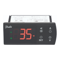
Other manuals for Danfoss ERC 211

Questions and Answers:

Question and Answer IconNeed help?

Do you have a question about the Danfoss ERC 211 and is the answer not in the manual?

Danfoss ERC 211 Specifications

General IconGeneral
BrandDanfoss
ModelERC 211
CategoryController
LanguageEnglish

Related product manuals