3.2. Mechanical Installation
3.2.1. Mechanical mounting
FC 300 IP 20 Frame sizes A1, A2 and A3, as well as IP 21/ IP 55 Frame sizes A5, B1, B2, C1 and
C2 allow side-by-side installation.
If the IP 21 Enclosure kit (130B1122 or 130B1123) is used, there must be a min. clearance of 2
in. [50 mm] between the drives.
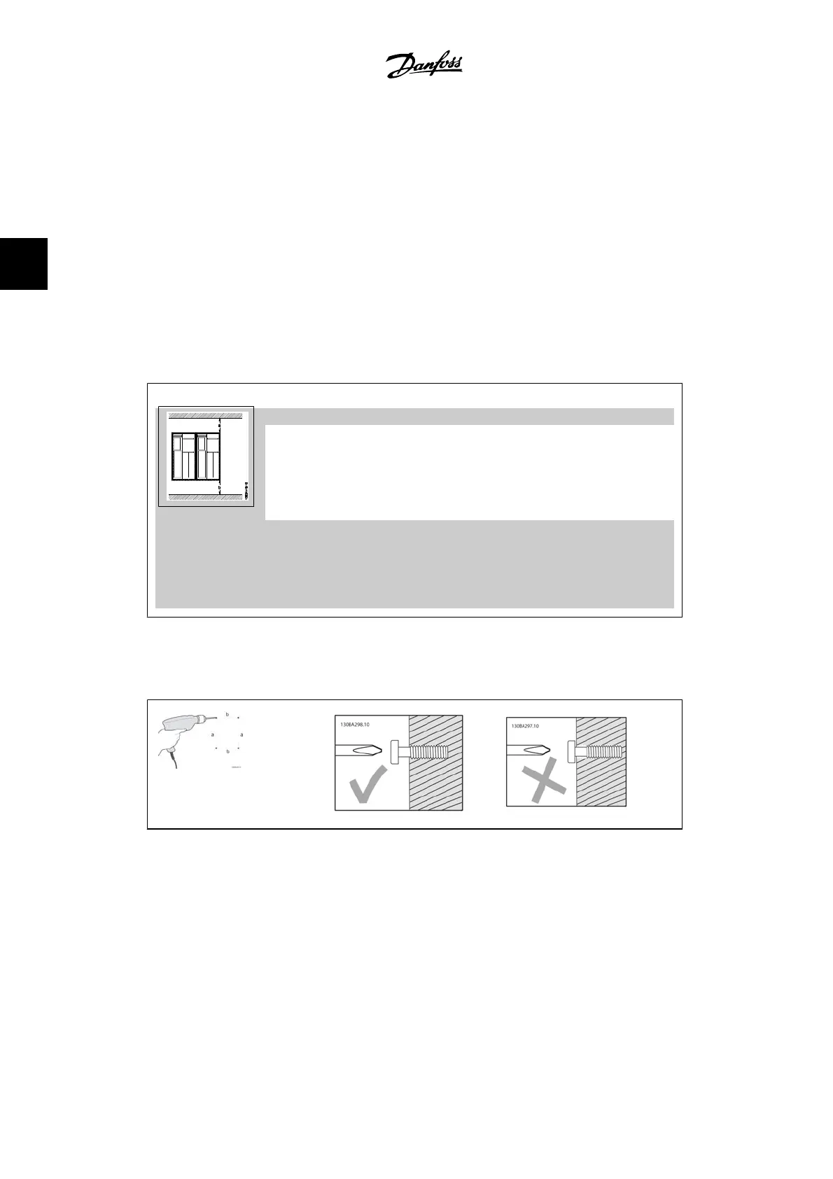
For optimal cooling conditions, allow a free air passage above and below the adjustable frequency
drive. See table below.
Air passage for different enclosures
Enclosure: A1 A2 A3 A5 B1 B2 C1 C2
a (mm): 100 100 100 100 100 100 200 225
b (mm): 100 100 100 100 100 100 200 225
1. Drill holes in accordance with the measurements given.
2. You must use screws that are suitable for the surface on which you want to mount the
FC 300. Retighten all four screws.
3. How to Install
VLT
®
AutomationDrive FC 300 Instruction
Manual
16
MG.33.A9.22 - VLT is a registered Danfoss trademark
3
 Loading...