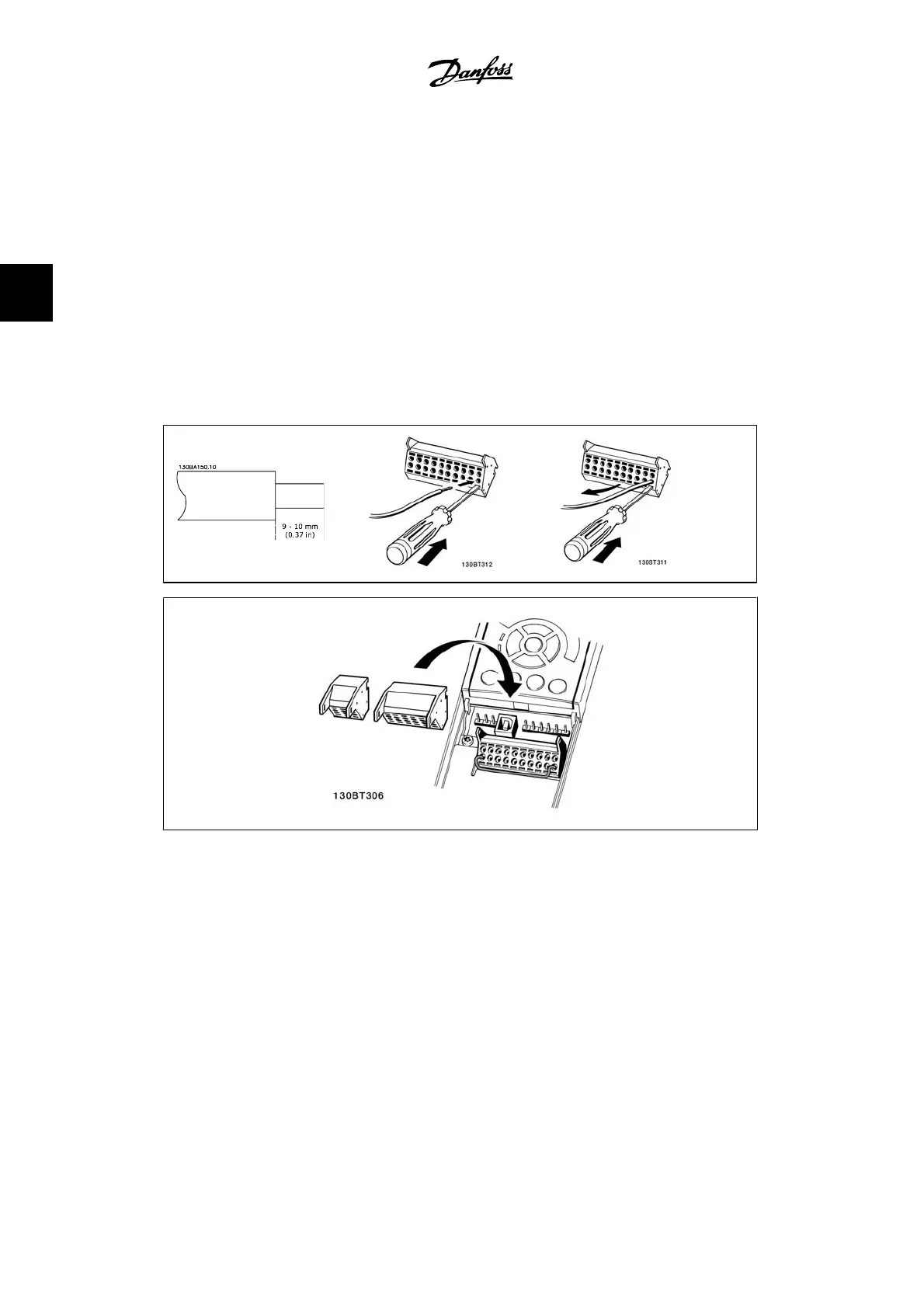
3.3.6. Electrical Installation, Control Terminals
To mount the cable to the terminal:
1. Strip isolation of 0.34-0.39 in [9-10 mm]
2.
Insert a screw driver
1)
in the square hole.
3. Insert the cable in the adjacent circular hole.
4. Remove the screwdriver. The cable is now mounted to the terminal.
To remove the cable from the terminal:
1.
Insert a screw driver
1)
in the square hole.
2. Pull out the cable.
1)
Max. 0.015 x 0.1 in. [0.4 x 2.5 mm]
1.
2.
3.
Assembling of IP 55 / NEMA Type 12 (A5 housing) with line supply disconnector
The line power switch is placed on the left side on the B1, B2, C1 and C2 enclosures. The line
power switch on the A5 enclosure is placed on the right side
3. How to Install
VLT
®
AutomationDrive FC 300 Instruction
Manual
34
MG.33.A9.22 - VLT is a registered Danfoss trademark
3
 Loading...