FCM 300 Series
MG.03.B6.02 - VLT is a registered Danfoss trademark28
■■
■■
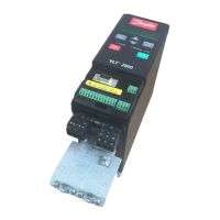
■ Control panel
The FC motor optionally features a Local Control
Panel - LCP 2 which makes up a complete
interface for operation and monitoring of the FC
motor.
NB!NB!
NB!NB!
NB!
The LCP from the VLT 5000 Series (code
number 175Z0401) cannot be used for the
FC motor. However, the general LCP 2 (code
number 175N0131) can be used for both the FCM
300, VLT 2800 and the VLT 5000 Series.
■■
■■
■ LCP installation
The LCP 2 is connected to the terminal X100, 1-4
(see separate instruction MI.03.AX.YY).
■■
■■
■ LCP functions
The functions of the control panel can be divided
into three groups:
● display
● keys for changing program parameters
● keys for local operation
All data are indicated by means of a 4-line alpha-
numeric display, which in normal operation is able to
show 4 measurements and 3 operating conditions
continuously. During programming, all the
information required for quick, effective parameter
3rd line is normally blank and is used in the menu
mode to show the selected parameter number or
parameter group number and name.
4th line is used in operating status for showing a
status text or in data change mode for showing the
value of the selected parameter.
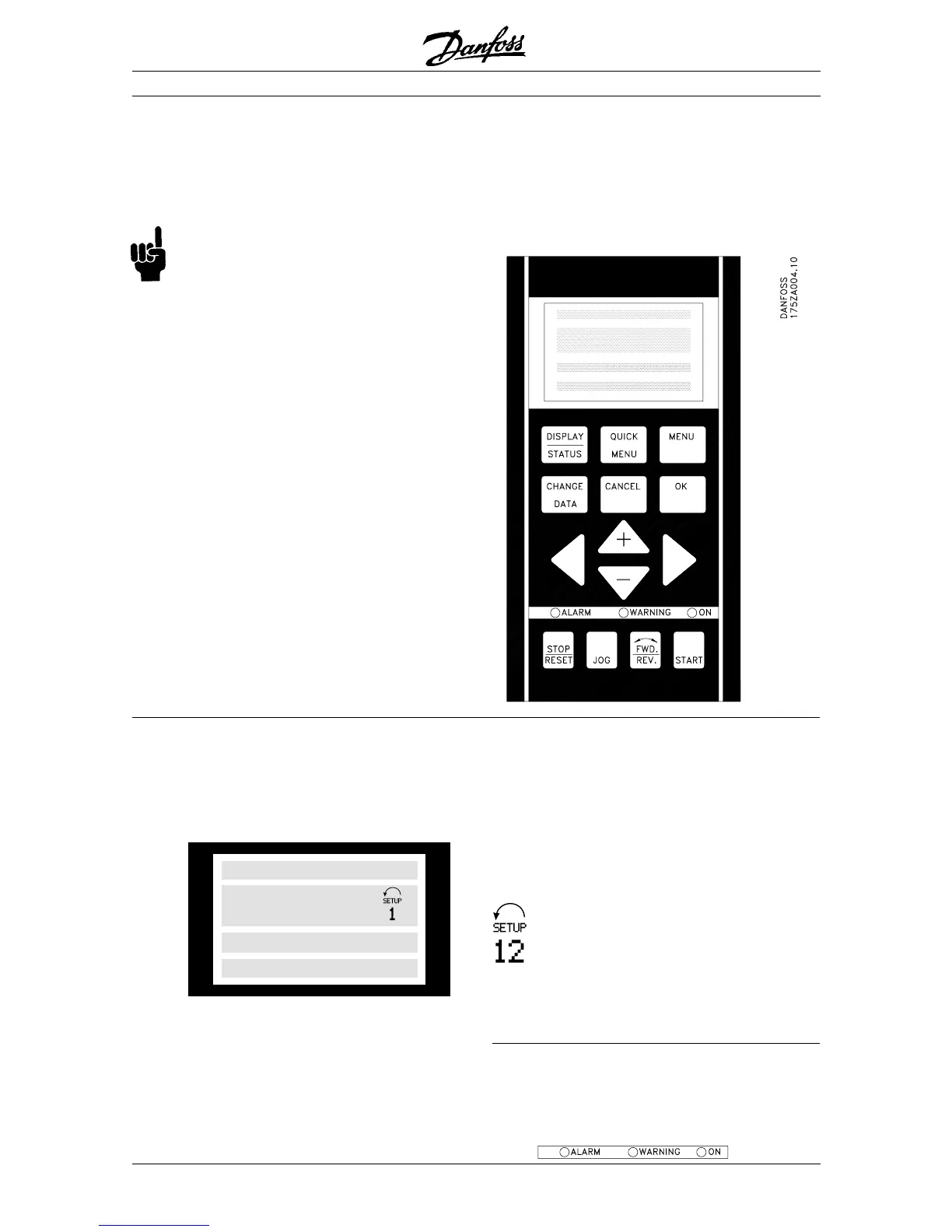
An arrow indicates the direction of rotation of
the motor. Furthermore, the Setup which has
been selected as the Active Setup in
parameter 004 is shown. When programming
another Setup than the Active Setup, the
number of the Setup which is being
programmed will appear to the right. This second
Setup number will flash.
■■
■■
■ LEDs
At the bottom of the control panel is a red alarm LED
and a yellow warning LED, as well as a green voltage
LED.
red yellow green
Local Control
■■
■■
■ Display
The LCD-display has rear lighting and a total of 4
alpha-numeric lines together with a box that shows
the direction of rotation (arrow) and the chosen Setup
as well as the Setup in which programming is taking
place if that is the case.
1st line
2nd line
3rd line
4th line
1st line shows up to 3 measurements continuously in
normal operating status or a text which explains the
2nd line.
2nd line shows a measurement with related unit
continuously, regardless of status (except in the case
of alarm/warning).
12345678901234567890
12345678
12345678901234567890
12345678901234567890
Setup of the FC motor will be displayed. As a
supplement to the display, there are three LEDs for
voltage, warning and alarm.
All program parameters of the FC motor can be
changed immediately from the control panel, unless
this function has been blocked via parameter 018.

 Loading...