4 | © Danfoss | FEC | 2020.03
AN29434614196101-000401 | 088N2112 00
Installation Guide Danfoss Icon™ Master Controller 24V
Content
Introduction ............................................................................................4
The Danfoss Icon™ family ...............................................................................4
Application .............................................................................................4
Installation .............................................................................................5
Optional installations ...................................................................................5
Setting up the system. . . . . . . . . . . . . . . . . . . . . . . . . . . . . . . . . . . . . . . . . . . . . . . . . . . . . . . . . . . . . . . . . . . . . . . . . . . . . . . . . . . 6
Connecting more Danfoss Icon™ Master Controllers in a system .........................................6
Test procedures for multiple Danfoss Icon™ Controllers in a system ......................................6
Slave type definition ....................................................................................6
Operation modes .......................................................................................7
Identifying an output from a room thermostat ..........................................................7
Removing units from a Danfoss Icon™ Master Controller 24V system .....................................7
Reset or replace a Danfoss Icon™ Master Controller 24V ..................................................7
Trouble shooting
.......................................................................................8
Hydraulic balance. . . . . . . . . . . . . . . . . . . . . . . . . . . . . . . . . . . . . . . . . . . . . . . . . . . . . . . . . . . . . . . . . . . . . . . . . . . . . . . . . . . . . . .8
Updating Firmware on Danfoss Icon™ 24V Master Controller .............................................8
Technical data ..........................................................................................9
Introduction
Danfoss Icon™ is a modular heating system for individual room control. It can be configured as a wired or wire-
less system or as a combination, if required.
The center of the system is the Danfoss Icon™ Master Controller 24V, which configures and ties the system
together.
Installation and set-up of the Danfoss Icon™ Master Controller 24V is easy and described in the included materials:
• The Quick Guide shows the most common installation with step-by-step illustrations, wired installation on
one side and wireless on the other.
• The Installation Guide describes the User Interface, installation in details and set-up in more complex
systems.
The Danfoss Icon™ family
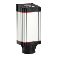
Wireless system components (pic. 1):
• Wireless Display Thermostat, 088U1081 (pic. 1.1)
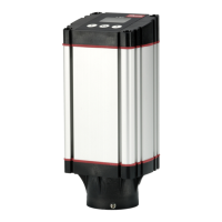
• Wireless Display Thermostat (Infrared), 088U1082 (pic. 1.2)
• Wireless Dial Thermostat, 088U1080 (pic. 1.3)
• Radio Module, 088U1103 (pic. 1.4)
• Repeater, 088U1102 (pic. 1.5)
Common system components (pic. 2):
• Expansion Module, 088U1100 (pic. 2.1)
• Master Controller 24V, 088U114x (multiple versions) (pic. 2.2)
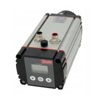
• App Module, 088U1101 (pic. 2.3)
• Dew Point Sensor, 088U0251 (pic. 2.4)
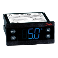
24V system components (pic. 3):
• 24V Display Thermostat, 088U105x (multiple versions) (pic. 3.1)
• 47 kΩ Floor Sensor, 088U1110 (pic. 3.2)
Application
Upon first installation the system is configured as a standard floor heating system. In this application the cir-
culation pump output (PWR1) and the potential free relay (RELAY) are both activated when there is a heat
demand.
Both the boiler relay (RELAY) and the pump output (PWR1) has a delay of 180 seconds in this application to
ensure there is flow through the circuits before the boiler and the pump are activated.
The use of mixing shunt, connection of circulation pump to Danfoss Icon™ Master Controller 24V and use of
boiler relay is optional, depending on application and available components.
To configure the Danfoss Icon™ Master Controller 24V system for other applications an Expansion Module
(code no. 088U1100) is required.
Application, Basic (pic. 4.1-4.2):
• 2-pipe system
• Mixing shunt (optional)
Pic. 4.2, A: RISK OF ELECTRIC SHOCK! Removing lid and installing 230 V wires should only be pre-
formed by a trained professional.
Parts list (pic. 4.1-4.2):
1. 1 pc. Danfoss FHM-Cx mixing shunt (optional) Part no. 088U0093/0094/0096
2. 1 set Danfoss Manifold Part no. 088U05xx (FHF), 088U06xx/0092 (BasicPlus)
or 088U07xx (SSM)
3. × pcs. TWA-A 24 V thermal actuators Part no. 088H3110 (NC), 088H3111 (NO)
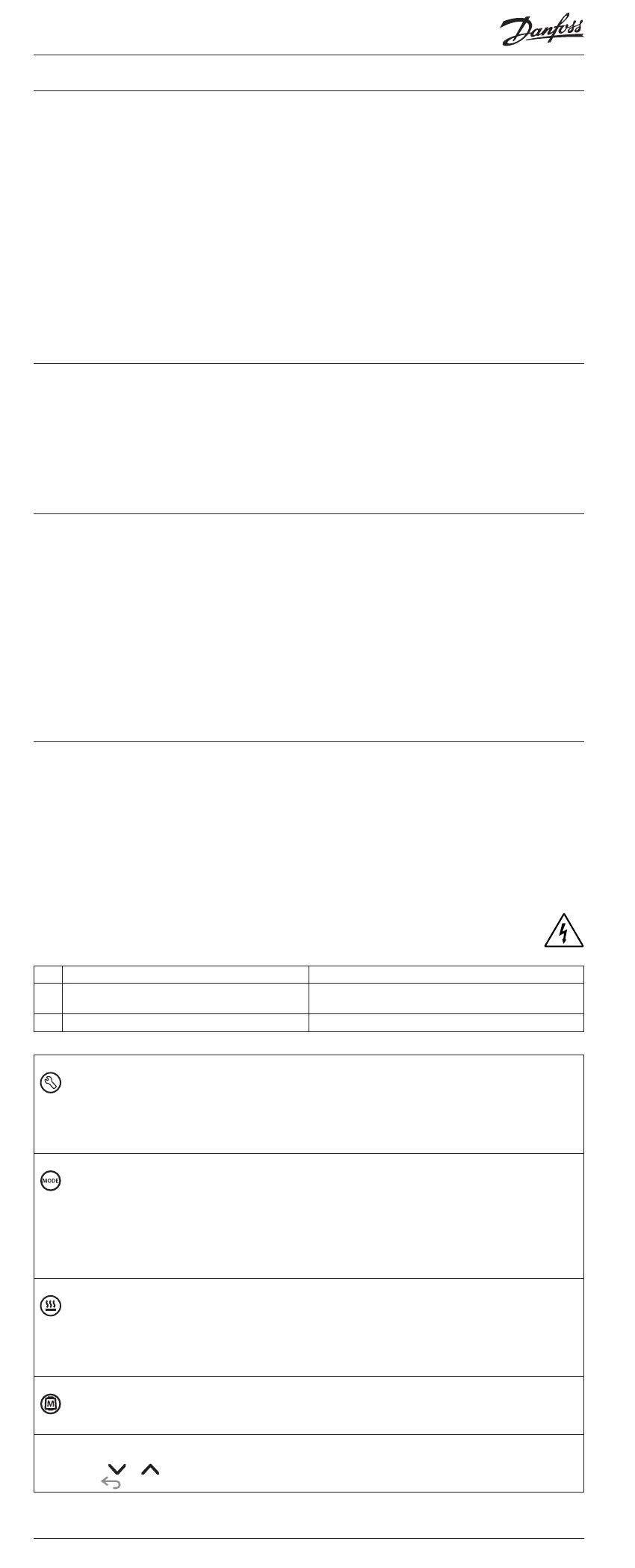
Keys:
1. Installer key
Used by the installer when setting up the system (used during installation).
• Select INSTALL for assigning thermostats and configuring the system.
• Select UNINSTALL for replacing or removing a system component, e.g. a thermostat.
• Select TEST for finalizing the installation and to run one of three test types, either: Network test,
Application test or Flow test (i.e. flushing the system for 20 minutes).
• Select RUN when all system devices are installed and a TEST is finished.
2.
Mode key
Used for choosing the desired control behavior of the entire system (set once for the entire system).
• PWM+: Type of regulation designed to minimize overheating by dividing the heat demand into
smaller bits (= duty cycles). The length of a duty cycle varies depending on the chosen heat emitter.
PWM+ also features auto balancing of flow to the different rooms, which improves the heating
comfort.
• On/Off: A simple hysteresis control, which turns on the heat when the temperature is below the
desired room temperature. The heat will not be turned off until the desired room temperature is
reached.
3.
Heat emitter key
Defines which heat emitter is used on the output (optimized control performance for each heat emit-
ter type).
• Select SLOW for floor construction with >50 mm concrete over pipes (typically no heat distribution
panels used).
• Select MEDIUM for floor or wall construction (typically pipes installed in heat distribution panels).
• Select FAST for radiator or convector (supplied from a manifold).
4.
Actuator type selector key
Used to define which kind of 24 V actuator is used (set once for the entire system).
• Select NC for normally closed (typically used).
• Select NO for normally open (rarely used).
5. Main user interface
• Press OK to confirm a setting.
• Press or to change a parameter value or toggle through menus.
• Use to go one step backwards in a menu.
 Loading...