User Guide | Optyma™ control AK-RC 113 three phase
18 | BC317523579312en-000101 © Danfoss | DCS (vt) | 2020.03
9.0 Appendices
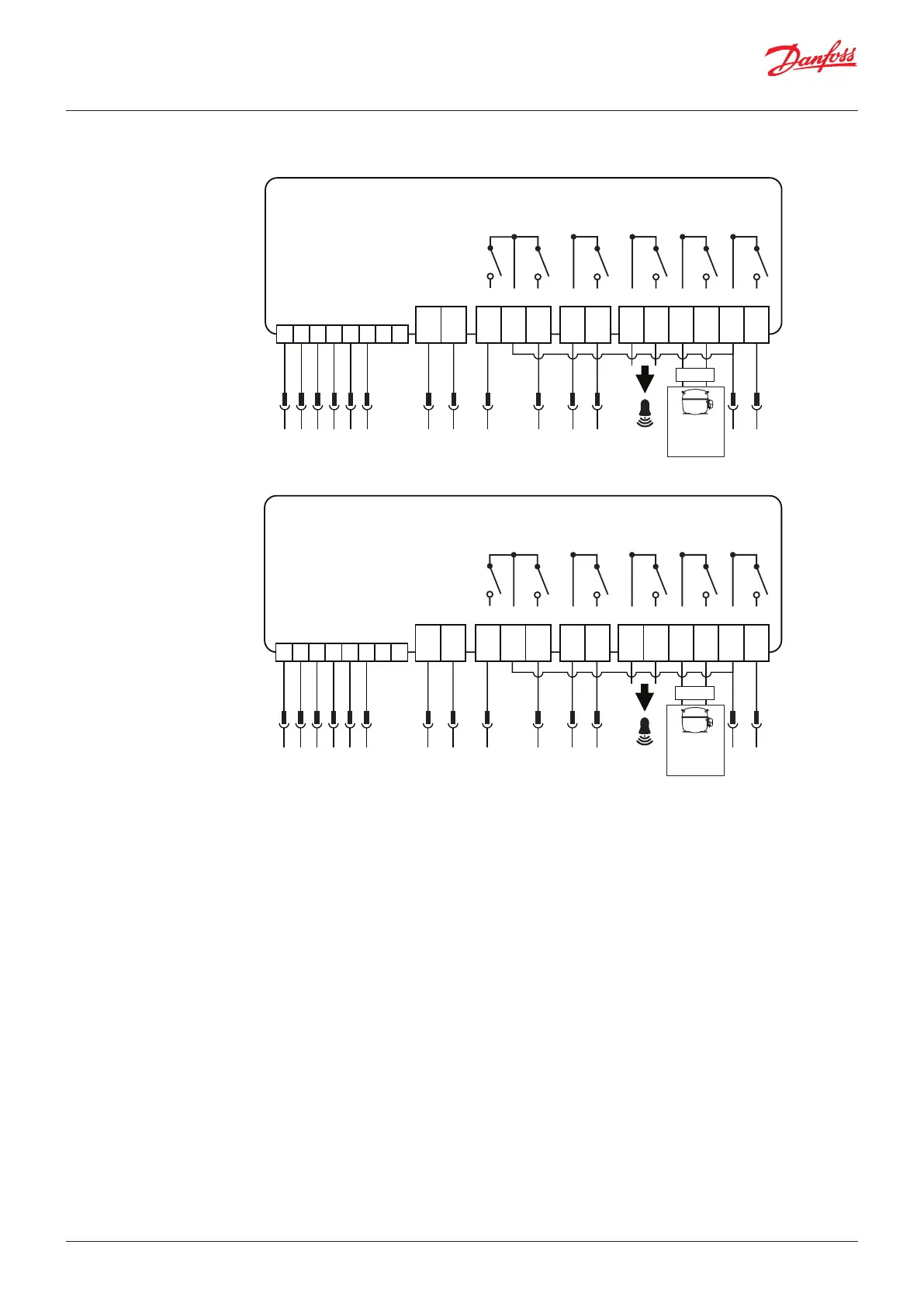
9.1 AK-RC 113 wiring diagram
1 2 3 4 5 6 7 8
9 10 11 12 13 14 15 16 17 20 21 18 19
JB01.1
12313 14 15
JB01.2
JB01.3
JB01.13
JB01.14
JB01.15
JB01.5
5
JB01.6
6
JB01.7
7
JB01.8
L8
JB01.4
4
JB01.9
9
JB01.10
L10
JB01.11
L11
1 2 3 4 5 6 7 8
9 10 11 12 13 14 15 16 17 20 21 18 19
JB01.1
12313 14 15
JB01.2
JB01.3
JB01.13
JB01.14
JB01.15
JB01.5
5
JB01.6
6
JB01.7
7
JB01.8
8
JB01.4
4
JB01.9
9
JB01.10
L10
JB01.11
L11
OPTYMA™ Control, three phase (4 HP)
OPTYMA™ Control, three phase (7.5 HP)
MODBUS B-
Power
Supply
230 V AC
Defrost Fans Compr. Aux1/All.
Condensing
unit
Electric
switchboard
enable
Aux2 Light
MODBUS A+
Defrost probe
Ambient probe
Common probes
Common dig. inputs
Door switch
Comp. protection
MODBUS B-
Power
Supply
230 V AC
Defrost Fans Compr. Aux1/All.
Condensing
unit
Electric
switchboard
enable
Aux2 Light
MODBUS A+
Defrost probe
Ambient probe
Common probes
Common dig. inputs
Door switch
Comp. protection
 Loading...