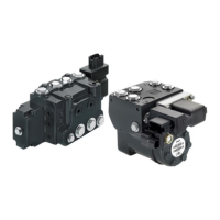
7-pin Layout
7-pin connector
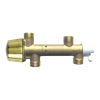
4-Pin layout
4-Pin connector, Group II
Versions Pin 1 Pin 2 Pin 3 Pin 4
PVEO-EX-24V, PVEO120-EX-24V U
DC
-A U
DC
-B GND —
PVEH/-EX/-U-EX, PVES/-EX/-U-EX, PVES120/-EX/-U-EX, PVEH120-EX U
s
V
bat
GND Error
Radiometric Control Signal
Radiometric control signal for PVEH/PVES
PIN Function of the pin Versions
1 U
S
Demand signal
PVES-EX
PVEH-EX
PVES120-EX
PVEH120-EX
PVEH-DI-EX
PVEH120-DI-EX
2 V
bat2
Supply voltage to solenoid valves (can be switched off separately)
3 GND Ground
4 Error Error pin (See PVE-EX fault monitoring on page 23)
5 GND DI-A Signal low when spool is stroked to A side (Only for DI versions)
6 GND DI-B Signal low when spool is stroked to B side (Only for DI versions)
7 V
bat
*
Supply voltage to DI versions
*
Pin 2 and 7 shall be connected together for PVE modules without the DI function.
Signal voltage (U
S
) Control
Neutral Q: P → A Q: P → B
U
S
= 0.5 • U
DC
U
S
= (0.5 → 0.25) • U
DC
U
S
= (0.5 → 0.75) • U
DC
Radiometric Fixed Control Signal (0-10 V)
Radiometric control signal for PVEH/PVES
PIN Function of the pin Versions
1 U
S
Demand signal
PVEH-U
PVES-U-EX
PVES120-U-EX
2 V
bat
Supply Voltage
3 GND Ground
4 Error Error pin (See PVE-EX fault monitoring on page 23)
Technical Information
Electrohydraulic Actuators PVE-EX
Specifications
12 |
©
Danfoss | October 2017 BC00000393en-US0102
 Loading...