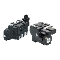
PVE-EX fault monitoring and reaction
PVE-EX is available with fault monitoring and spool direction indication.
The fault monitoring system is available in two versions:
•
Active fault monitoring provides a warning signal and deactivates the solenoid valves. A reboot of the
PVE is required to reactivate.
•
Passive fault monitoring provides a warning signal only. A reboot is not required.
Both active and passive fault monitoring systems are triggered by the same three main events:
•
Control signal monitoring
•
Transducer supervision
•
Supervision of spool position
Control signal monitoring
The Control signal voltage (US) is continuously monitored. The permissible range is between 15% and
85% of the supply voltage. Outside this range the PVE-EX will switch into an error state.
Transducer supervision
The internal LVDT wires are monitored. If the signals are interrupted or short-circuited, the PVE-EX will
switch into an error state.
Supervision of spool position
The actual position must always correspond to the demanded position (US).
If the actual spool position is further out from neutral than the demanded spool position >12% or in
opposite direction, the PVE will switch into an error state.
With neutral/blocked setpoint the tolerance is +- 0.5 mm relative the calibrated neutral position. Spool
position closer to neutral and in same direction will not cause an error.
•
Active fault reaction is activated when the failure has been active for 500 ms
‒
The solenoid valve bridge is disabled and the PVBS is released to spring control
‒
The error output pin goes high
‒
The state is memorized and continues until PVE reboot
•
Passive fault reaction is activated when the failure has been active for 500 ms
‒
The solenoid valve bridge is NOT disabled and the PVBS is NOT released
‒
The error output pin goes high (for PVE with direction indication both DI pins goes low by fault)
‒
The state is active for minimum 100 ms and is reset when error disappears
To avoid the electronics in undefined state a general supervision of power supply (UDC) an internal clock
frequency is implemented. This function applies to PVEH and PVES independently of fault monitoring
version and will not activate fault monitoring.
Warning
Error pins from more PVEs may not be interconnected. Not activated error pins are connected to ground
and will disable any active signal. Error pins are signal pins and can only supply very limited power
consumption.
•
The solenoid valves are disabled when
Technical Information
Electrohydraulic Actuators PVE-EX
Safety and monitoring
22 |
©
Danfoss | October 2017 BC00000393en-US0102
 Loading...