Signal voltage (U
S
) Control
Neutral Q: P → A Q: P → B
U
S
= 5 V U
S
= 5 V → 2.5 V U
S
= 5 V → 7.5 V
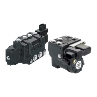
Radiometric Control Signal – On/Off Activation
Radiometric control signal for PVEO versions
PIN Function of the pin Versions
1 U
DC
(A) Input signal direction A
PVEO-EX-12V
PVEO-EX-24V
PVEO-DI-EX-24V
PVEO120-EX-24V
PVEO120-DI-EX-12V
2 U
DC
(B) Input signal direction B
3 GND Ground
4 GND Ground
5 DI-A Signal low when spool is stroked to A side (Only for DI
versions)
6 DI-B Signal low when spool is stroked to B side (Only for DI
versions)
7 V
bat
Supply voltage to DI versions
Signal voltage Control
Signal voltage Neutral Q: P → A Q: P → B
A 0 U
DC
(A) 0
B 0 0 U
DC
(B)
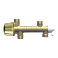
Adjustment/calibration
The PVE-EX is pre-calibrated from the factory to be inside the dead band of the proportional valve. The
position sensor built into the PVE-EX cannot be adjusted by user. Any biasing of the position has to be
incorporated in the demand signal.
Technical Information
Electrohydraulic Actuators PVE-EX
Specifications
©
Danfoss | October 2017 BC00000393en-US0102 | 13
 Loading...