4
Installation
IMPORTANT: The supply to this unit should by wired via a full
disconnect in accordance with BS EN60730-1, i.e. one which
provides air gaps of at least 3mm in both poles of the mains, and
incorporates a 3 amp fuse. It is strongly recommended that solid
conductors be used.
Please note: If replacing an existing TP9, please check warranty expiry
date of the defective product. If date precedes June 2005, the remote
sensor must also be changed.
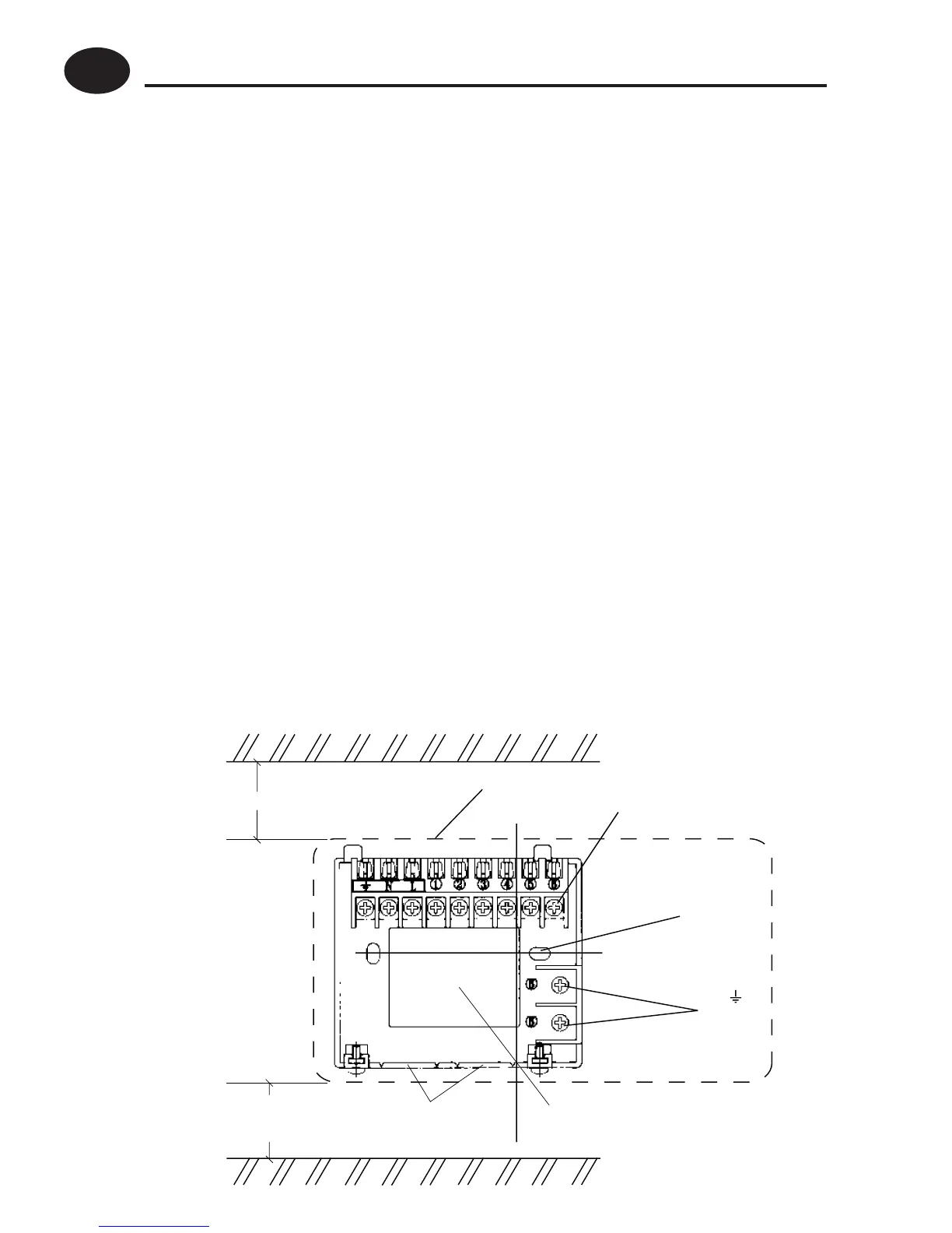
First, remove the wallplate from the back of the unit.
When fi xing the wallplate remember the connections are at
the top and the vertical centre line of the unit is at the position
shown C/L, (which is at the right hand edge of the terminal 4
recess).
Clearance for
screwdriver
access
Surface fixed cable
bottom entry knockouts
Rear entry
cable access
N &
looping
terminals
Wall or
Plaster box
fitting
Terminal block
Outline of unit
30mm minimum
C/L
!
Installation Instructions
GB
 Loading...