5
Fix the wallplate to the wall or fl ush mounted box as required.
Surface cables can only enter from below the unit. If mounted
on a fl ush mounted box, cables can enter from the rear
through the aperture in the wallplate.
Whilst the unit does not require an Earth connection, two
terminals are provided on the wallplate for Earth continuity
purposes.
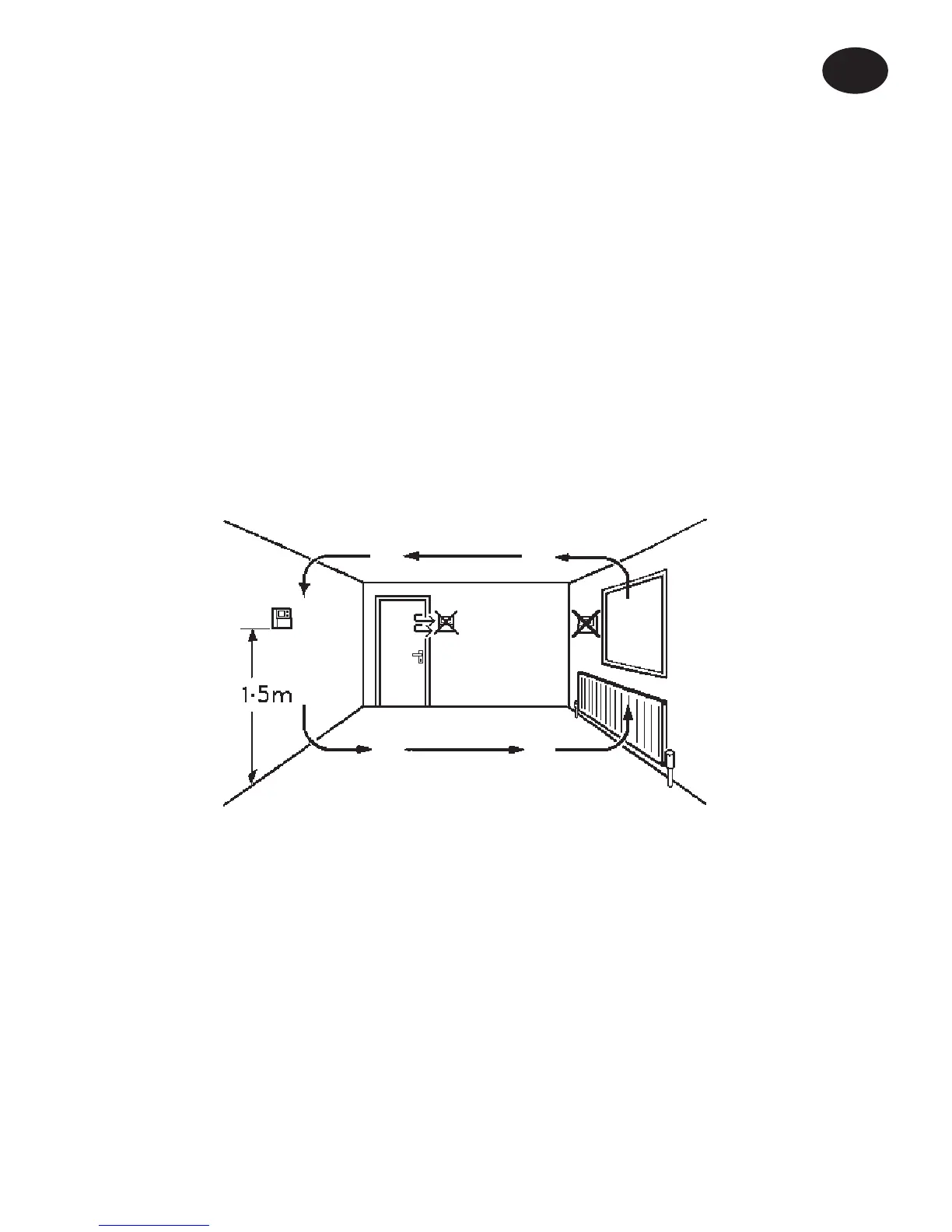
Locate and fi x the Remote Sensor 1.5m above fl oor, away from
draughts and extraneous heat gains. Remote Sensor wiring
should be in 1mm
2
Mains Voltage Cable (not fl exible cord).
Sensor cable must not be run parallel to mains cable in order
to avoid pick-up.
For wiring connections refer to diagrams on pages 7-13.
Set the unit for either 24 hour or 5/2 day operation. It is supplied
ready for 5/2 day operation, and in the unlinked PUMPED
primaries condition. To convert it to 24 hour operation move
the Switches 2 and 3 on the back of the unit to the 24 HR
position. To operate in the linked GRAVITY condition move
Switch 1 to the GRAVITY position.
Installation Instructions
GB
 Loading...