FCM 300 / FCD 300 / VLT
®
2800 / DP V1 PROFIBUS
The Profibus
Interface
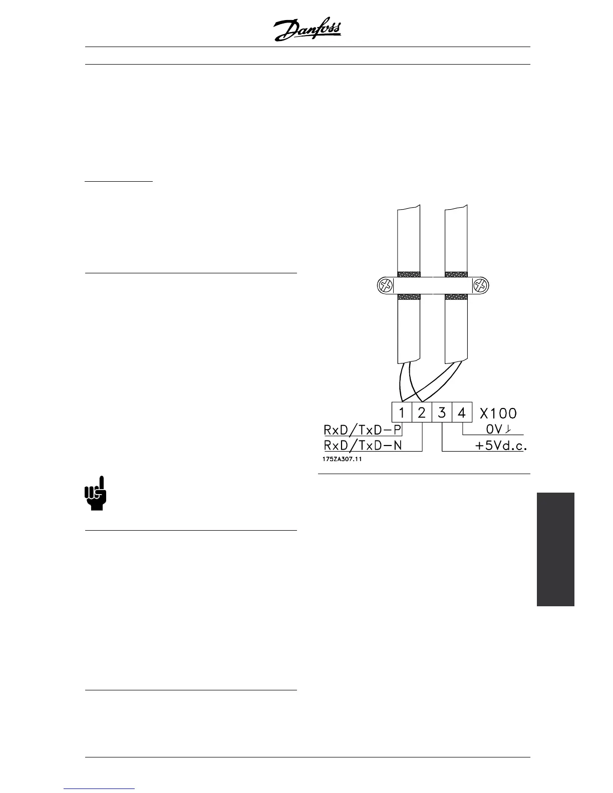
■ Physical connection
The PROFIBUS is connected to the b us line
via X100, terminals 1 and 2.
It is recommended to use a master with a
galvanic isolated bus driver and with over voltage
protection (e.g. zenerdiode).
E
MC precautions
The following EMC precautions are recommended to
obtain interference free operation o f the PROFIBUS
network. Additional information on EMC can be found
in the design guide on the FCM 300 (MG.03.BX.02).
Please also consult the manual of the PROFIBUS
master for further installation guidelines.
■ Connection of the cable screen
The screen of the PROFIBUS c able must always
be connected to ground at both ends, that means
the screen must be connected to ground in all
stations connected to the PROFIBUS network. It
is very important to have a low impedance ground
connection of the screen, also at high frequencies.This
can be obtained by connecting the surface of the
screen to ground, fo r example by m eans of a cable
clamp or a conductive cable gland.
The FCM 300 Series is provided with different clamps
and brackets to enable a proper ground conn ection of
the PROFIBUS cable screen. The screen connection
is shown in the following drawing.
NB!:
Relevant national and local regulations,
for example regarding protective earth
connection, must be observed.
■ Cable connection FCM 300
The PROFIBUS communication cable must be kept
away from motor a nd brake resistor cab les to avoid
coupling of high frequency noise from one cable to
the other. Normally a distance of 200 mm is sufficient,
but it is generally recommended to keep the greatest
possible distance between the cables, especially whe re
cables are running in parallel over long distances.
If the PROFIBUS cable has to cross a motor and
braking resistance cable, i t should occur a t a 90° angle.
■ Earth connection
It is important that all stations connected to the
PROFIBUS network are connected to the same
earth potential. The earth connection must have
a low HF (high frequency) impedance. This c an
be achieved by connecting a large surface area of
the cabinet to earth, for example by mounting the
FC motor on a conductive rear plate.
Especially when having long distances between the
stations in a P ROFIBUS network it can be necessary to
use additional potentia l equalizing cables, c onnecting
the individual stations to the same earth potential.
MG.90.A5.02 - VLT is a registered Danfoss trademark
11
 Loading...


