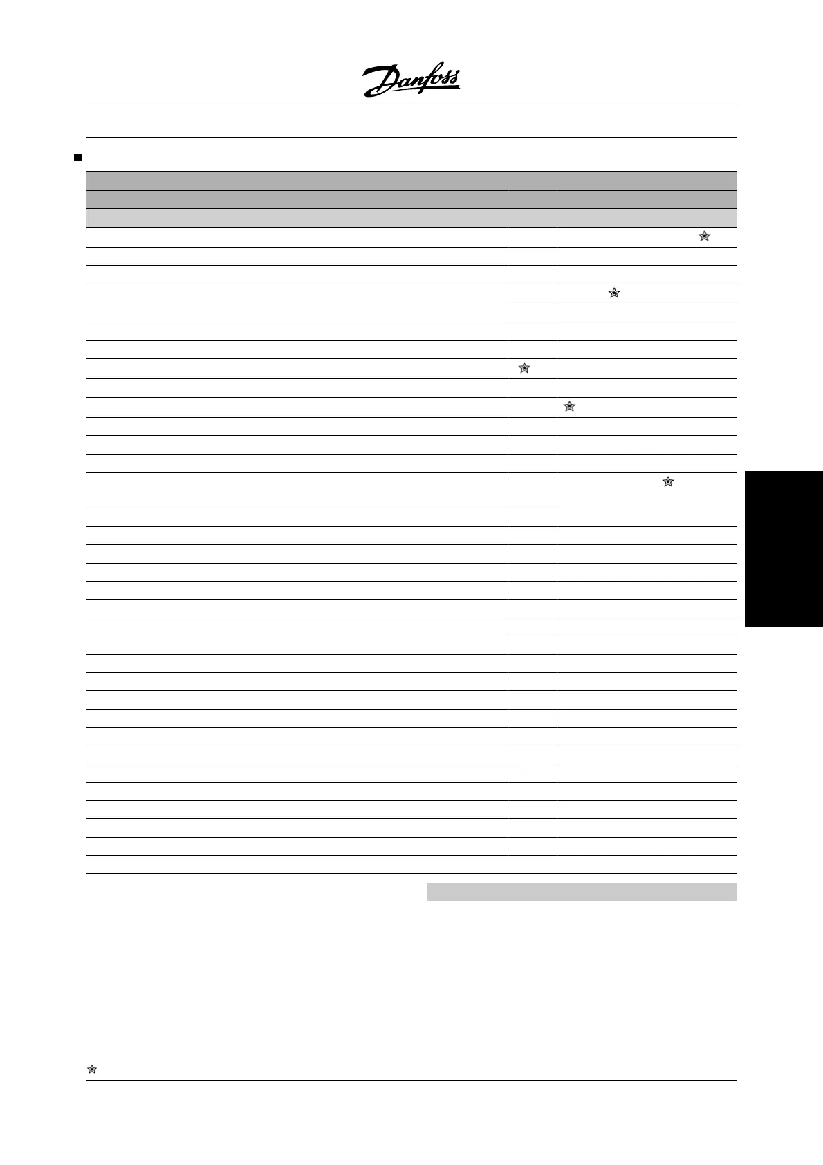
Inputs and Outputs
Digital inputs Term. no.
18
1
19
1
27 29 33
par. no. 302 303 304 305 307
Value:
No function (NO OPERATION) [0] [0] [0] [0]
[0]
Reset (RESET) [1] [1] [1] [1] [1]
Coasting stop inverse (MOTOR COAST INVERSE) [2] [2] [2] [2] [2]
Reset and coasting inverse (RESET AND COAST INV.) [3] [3]
[3]
[3] [3]
Quick-stop inverse (QUICK-STOP INVERSE) [4] [4] [4] [4] [4]
DC braking inverse (DC BRAKE INVERSE) [5] [5] [5] [5] [5]
Stop inverse (STOP INVERSE) [6] [6] [6] [6] [6]
Start (START)
[7]
[7] [7] [7] [7]
Pulse start (LATCHED START) [8] [8] [8] [8] [8]
Reversing (REVERSING) [9]
[9]
[9] [9] [9]
Reversing and start (START REVERSING) [10] [10] [10] [10] [10]
Start clockwise (ENABLE FORWARD) [11] [11] [11] [11] [11]
Start counter-clockwise (ENABLE REVERSE) [12] [12] [12] [12] [12]
Jog (JOGGING) [13] [13] [13]
[13]
[13]
Freeze reference (FREEZE REFERENCE) [14] [14] [14] [14] [14]
Freeze output frequency (FREEZE OUTPUT) [15] [15] [15] [15] [15]
Speed up (SPEED UP) [16] [16] [16] [16] [16]
Slow (SLOW) [17] [17] [17] [17] [17]
Catch-up (CATCH-UP) [19] [19] [19] [19] [19]
Slow-down (SLOW-DOWN) [20] [20] [20] [20] [20]
Ramp 2 (RAMP 2) [21] [21] [21] [21] [21]
Preset ref, LSB (PRESET REF, LSB) [22] [22] [22] [22] [22]
Preset ref, MSB (PRESET REF, MSB) [23] [23] [23] [23] [23]
Preset reference on (PRESET REFERENCE ON) [24] [24] [24] [24] [24]
Thermistor (THERMISTOR) [25] [25] [25] [25]
Precise stop, inverse (PRECISE STOP INV.) [26] [26]
Precise start/stop (PRECISE START/STOP) [27] [27]
Pulse reference (PULSE REFERENCE) [28]
Pulse feedback (PULSE FEEDBACK) [29]
Pulse input (PULSE INPUT) [30]
Selection of Set-up, lsb (SET-UP SELECT LSB) [31] [31] [31] [31] [31]
Selection of Set-up, msb (SET-UP SELECT MSB) [32] [32] [32] [32] [32]
Reset and start (RESET AND START) [33] [33] [33] [33] [33]
Pulse counter start (PULSE COUNTER START) [34] [34]
1. All functions on terminals 18 and 19 are controlled
by an interrupter, which means that the repetitive ac-
curacy of the response time is constant. Can be used
for start/stop, set-up switch, and especially for chang-
ing digital preset, i.e., to obtain a reproducible stop
point when using creep speed. For further information,
see VLT 2800 Precise Stop Instruction, MI.28.CX.02.
Function:
In these parameters, 302-307 Digital inputs, it is pos-
sible to choose between the different enabled func-
tions related to the digital inputs (terminals 18-33).
VLT
®
2800 Series
= factory setting, () = display text, [] = value for use in communication via serial communication port
MG.27.A2.22 - VLT
®
is a registered Danfoss trademark 59
Programming
 Loading...


