139MG.30.A7.02 - VLT
®
is a registered Danfoss trademark
Harmonic currents compared to the RMS
input current:
The value of I
1
is equivalent to the power
factor.
Power factor
3 x V x I
1
x cosϕ
1
3 x V x I
RMS
I
1
x cosϕ
1
I
RMS
I
RMS
= I
1
2
+I
5
2
+I
7
2
+ . . . + I
n
2
Mains supply
interference / harmonics
A frequency converter takes up a non-
sinusoidal current, which will increase the
input current I
RMS
. A non-sinusoidal current
can be transformed by means of a Fourier
analysis and split up into sine wave cur-
rents with different frequencies, this means
different harmonic currents I
N
with 50 Hz as
the basic frequency:
The harmonic currents do not contribute
directly to the power consumption, but
increase the heat losses in the installation
(transformer, cables). Therefore, in plants
with a rather high percentage of rectifier
load, it is important to maintain harmonics
at a low level to avoid overload of the
transformer and high temperature in the
cables.
Some of the harmonics might disturb com-
munication equipment connected to the
same transformer or cause resonances in
connection with power-factor correction
equipment.
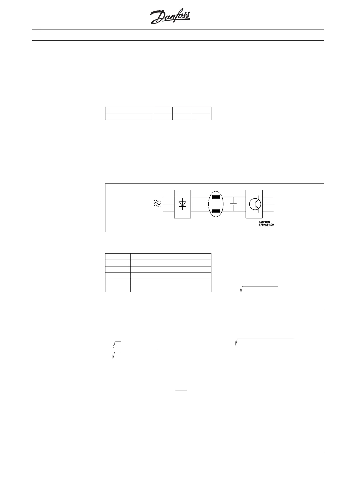
Due to the above it is important to sup-
press these harmonics. The most common
method is to mount coils in the mains sup-
ply to the frequency converter or in the in-
termediate circuit of the frequency con-
verter. Coils in the intermediate circuit give
the advantage of a lower voltage drop
compared to the coils in the mains connec-
tion.
As standard the VLT
®
series 3000 has coils
in the intermediate circuit for effective sup-
pression of the harmonic currents.
Harmonic currents I
1
I
5
I
7
Hz 50 Hz 250 Hz 350 Hz
Input current
I
RMS
1.0
I
1
0.9
I
5
0.4
I
7
0.2
I
11-49
< 0.1
The voltage distortion of the mains supply
depends on the size of the harmonic
currents multiplied by the internal imped-
ance for the relevant frequency.
The total voltage distortion THD is calcu-
lated on the individual voltage harmonics
according to the following formula:
THD% = U
1
+ U
5
+
.....
U
N
Furthermore, a high power factor indicates
that the different harmonic currents are low.
(U
N
% of U)
=
Power factor =
Mains supply interference / harmonics - Power factor
The power factor is the ratio between
power (kW) and total (kVA).
Power factor for 3-phased supply
cosϕ
1
≈ 1 ⇒ power factor ≈
I
RMS
I
1
The power factor indicates the frequency
converter’s load on the supply mains. The
lower the power factor, the higher (I
RMS
) for
the same kW.
Artisan Technology Group - Quality Instrumentation ... Guaranteed | (888) 88-SOURCE | www.artisantg.com
 Loading...


