Synchronizing controller
MG.10.N4.02 - VLT is a registered Danfoss trademark 19
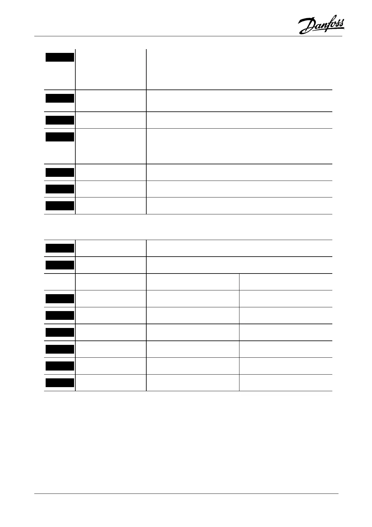
4
O4 - Brake control
This output can be used to control a mechanical brake.
“0” means that the brake must be closed (braking)
“1” means that the brake must be open (not braking)
5
O5 - Saving
This output stays high while saving is in progress. The saving is
initiated by Parameter 710, Input 4 or fieldbus bit 4.
6
O6 - Drive running
Signal “1” when the drive is running.
7
O7 - Home reached
Synchronous operation; Program 2:
If the data value “1” or “2” was chosen in Parameter 729, this
output shows “1” homing is completed.
8
O8 - Ready, no error
The Synchronizing controller is ready for operation.
9
24V DC
10
COM
Option card MK3D (slave encoder)
1
5V DC
Encoder supply
2
COM
Encoder supply
Incremental encoder Absolute encoder
3
A1
A-track Clock out
4
/A1
A-track inverted Clock out inverted
5
B1
B-track Data in
6
/B1
B-track inverted Data in inverted
7
Z1
Zero-track Not used
8
/Z1
Zero-track inverted Not used

 Loading...


