Control with brake function
The function of the brake is to limit the voltage in the
intermediate circuit when the motor is acting as a gen-
erator. This occurs, for example, when the load drives
the motor and the power enters the intermediate cir-
cuit. The brake is built up in the form of a chopper
circuit with the connection of an external brake resis-
tor. Placing the brake resistor externally offers the
following advantages:
-
The brake resistor can be selected on the
basis of the application in question.
-
The brake energy is dissipated outside the
control panel, i.e. where the energy can be
utilized.
-
The electronics of the adjustable frequency
drive will not be overheated if the brake re-
sistor is overloaded.
The brake is protected against short-circuiting of the
brake resistor, and the brake transistor is monitored to
ensure that short-circuiting of the transistor is detec-
ted. By using a relay/digital output, the latter can be
used for protecting the brake resistor against over-
loading in connection with a fault in the adjustable
frequency drive.
In addition, the brake makes it possible to read out the
momentary power and the mean power for the latest
120 seconds, as well as to monitor that the power en-
ergizing does not exceed a monitoring limit selected
via parameter 402. In parameter 403 select the func-
tion to be carried out when the power transmitted to
the brake resistor exceeds the limit set in parameter
402.
NOTE
Monitoring of the brake power is not a
safety function; a thermal switch is re-
quired for that purpose. The brake resistor
circuit is not earth leakage protected.
Selection of Brake Resistor
In order to select the right brake resistor, information
on how often to brake and by the level power braking
is effected must be available.
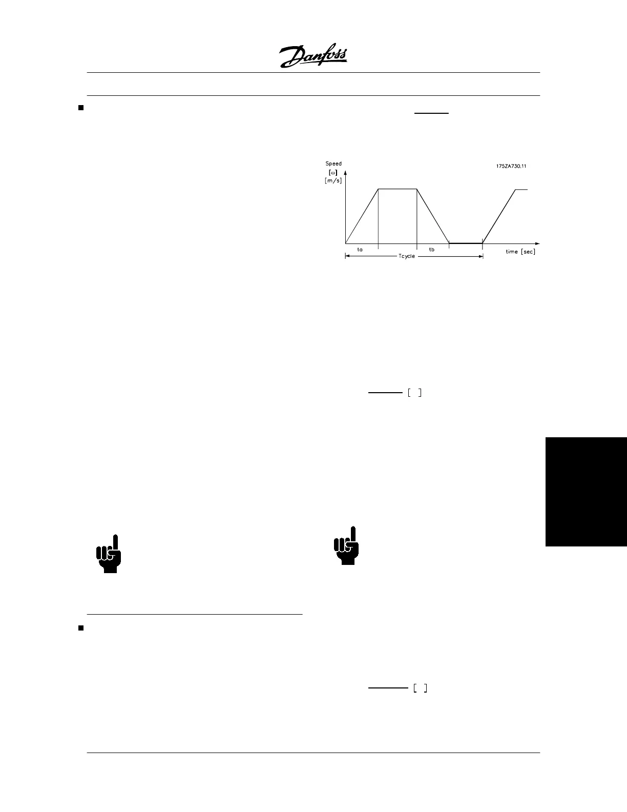
The resistor ED is an indication of the duty cycle at
which the resistor is working.
The resistor ED is calculated as follows:
ED
(
duty cycle
)
=
tb
T cycle
where tb is the braking time in seconds and T cycle is
the total cycle time.
The maximum permissible load on the brake resistor
is stated as a peak power at a given ED. The following
example and formula apply to VLT 5000 only. The
peak power can be calculated on the basis of the high-
est brake resistance required for braking:
P
PEAK
= P
MOTOR
x M
BR(%)
x •
MOTOR
x •
VLT
[W]
where M
BR(%)
is a percentage of the rated torque.
The brake resistance is calculated as follows:
R
REC
=
U
2
DC
P
PEAK
ˑ
The brake resistance depends on the intermediate cir-
cuit voltage (UDC).
The brake will be active at the following voltages:
• 3 x 200-220 V: 397 V
• 3 x 380-500 V: 822 V
• 3 x 525-600 V: 943 V
• 3 x 525-690 V: 1084 V
NOTE
The brake resistor used must be rated to
430 Volts, 850 Volts, 960 Volts or 1100
Volts, unless Danfoss brake resistors are
used.
R
REC
is the resistance recommended by Danfoss, i.e.,
one that guarantees the user that the adjustable fre-
quency drive is able to brake at the highest braking
torque (M
br
) of 160%.
•
motor
is typically at 0.90, while •
VLT
is typically at 0.98.
R
REC
at 160% braking torque can be written as:
R
REC
=
111.684
P
MOTOR
ˑ
at
200
V
VLT
®
5000 Series
MG.51.C5.22 - VLT
p
is a registered Danfoss trademark. 189
List of functions
 Loading...


