3.2.7 Installation on the Wall - IP21 (NEMA
1) and IP54 (NEMA 12) Units
This only applies to enclosure types D1 and D2. It must be
considered where to install the unit.
Take the relevant points into consideration before
selecting the final installation site:
•
Free space for cooling
•
Access to open the door
•
Cable entry from the bottom
Mark the mounting holes carefully using the mounting
template on the wall and drill the holes as indicated.
Ensure proper distance to the floor and the ceiling for
cooling. A minimum of 225 mm (8.9 inch) below the
frequency converter is needed. Mount the bolts at the
bottom and lift the frequency converter up on the bolts.
Tilt the frequency converter against the wall and mount
the upper bolts. Tighten all 4 bolts to secure the frequency
converter against the wall.
Illustration 3.35 Lifting Method for Mounting Frequency
Converter on Wall
3.2.8
Gland/Conduit Entry - IP21 (NEMA 1)
and IP54 (NEMA12)
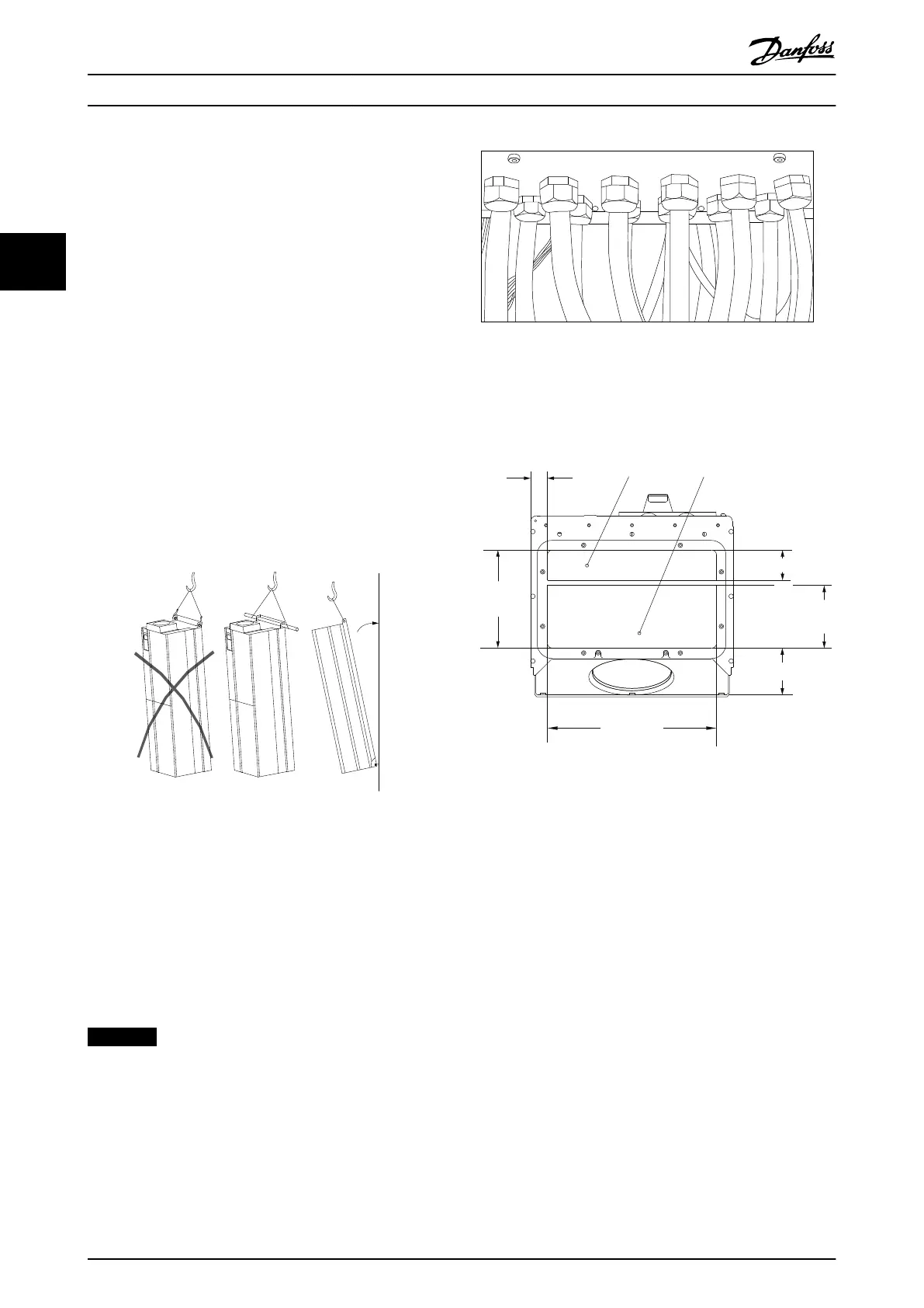
Cables are connected through the gland plate from the
bottom. Remove the plate and plan where to place the
entry for the glands or conduits. Prepare holes in the
marked area on the drawing.
NOTICE
The gland plate must be fitted to the frequency
converter to ensure the specified protection degree, as
well as ensuring proper cooling of the unit. If the gland
plate is not mounted, the frequency converter may trip
on Alarm 69, Pwr. Card Temp
Illustration 3.36 Example of Proper Installation of Gland Plate.
Cable entries viewed from the bottom of the frequency
converter - 1) Mains side 2) Motor side
2
1
176FA289.12
35
350
202.8
98.6
130.0
62.5
Illustration 3.37 Enclosure Types D1 + D2
How to Install
VLT
®
Automation Drive FC 300 Operating Instructions
34 MG33U402 - Rev. 2013-12-16
33
 Loading...


