EXAMPLE 2:
Variable= FEEDBACK, range= -200% to +200%
Range needed for output= 0-100%
Output signal 0 or 4 mA is needed at 0% (50% of range) - set par. 6-51 to 50%
Output signal 20 mA is needed at 100% (75% of range) - set par. 6-52 to 75%
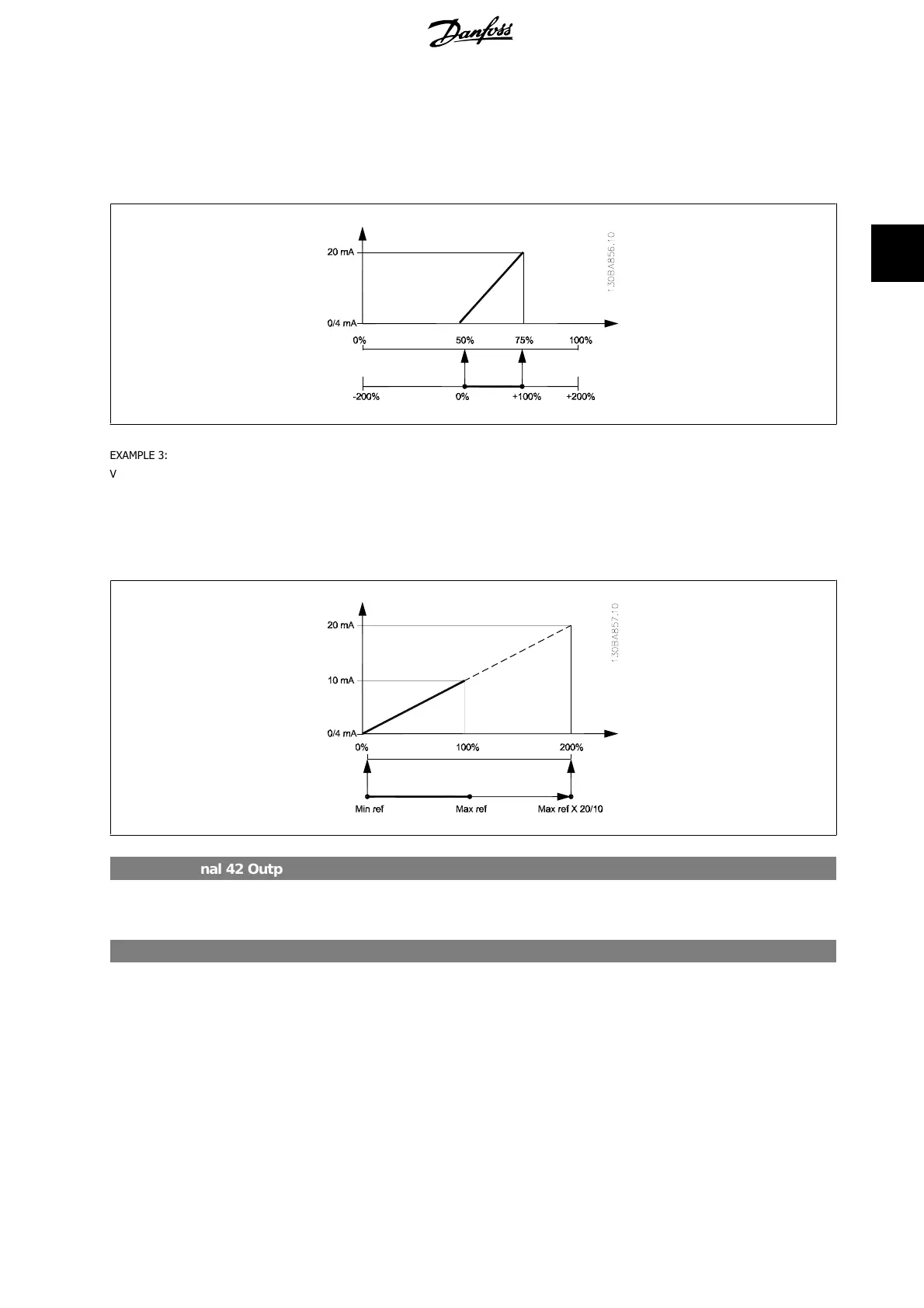
EXAMPLE 3:
Variable value= REFERENCE, range= Min ref - Max ref
Range needed for output= Min ref (0%) - Max ref (100%), 0-10 mA
Output signal 0 or 4 mA is needed at Min ref - set par. 6-51 to 0%
Output signal 10 mA is needed at Max ref (100% of range) - set par. 6-52 to 200%
(20 mA / 10 mA x 100%=200%).
6-53 Terminal 42 Output Bus Control
Range: Function:
0.00%
*
[0.00 – 100.00 %]
Holds the level of Output 42 if controlled by bus.
6-54 Terminal 42 Output Timeout Preset
Range: Function:
0.00%
*
[0.00 – 100.00 %]
Holds the preset level of Output 42.
In case of a bus timeout and a timeout function is selected in par. 6-50 the output will preset to this level.
3.8.8. 6-6* Analog Output 2 (MCB 101)
Analog outputs are current outputs: 0/4 - 20 mA. Common terminal (terminal X30/8) is the same terminal and electrical potential for analog common
connection. Resolution on analog output is 12 bit.
VLT
®
HVAC Drive Programming Guide 3. Parameter Description
MG.11.C5.02 - VLT
®
is a registered Danfoss trademark
87
3
 Loading...


