7. Application Examples
7.1. Example: Working with Instance 101/151 Process
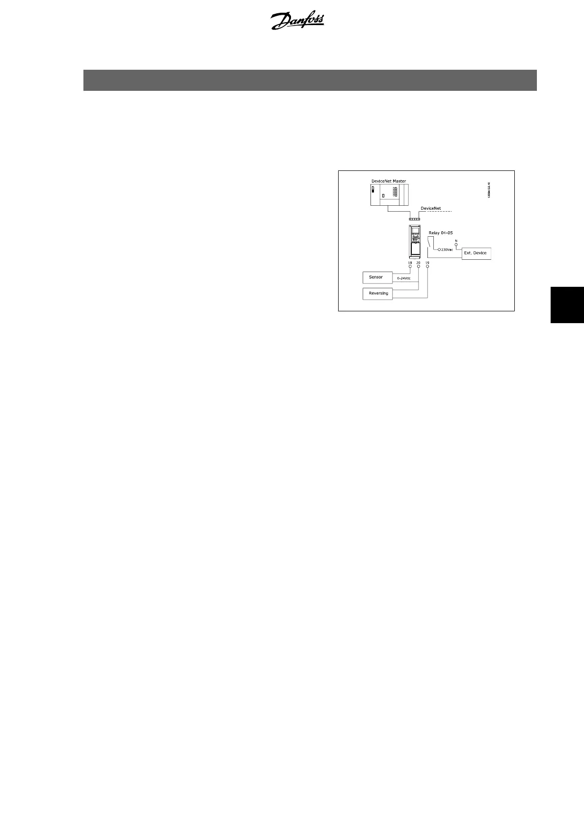
This example shows how to work with I/O In-
stance 101/151, which consists of Control
Word/Status Word and Reference/Main Actual
Value. The Instance 101/151 also has two ad-
ditional words, which can be programmed to
monitor process signals, as shown in the fig-
ure.
The application requires monitoring of the
motor torque and digital input, so PCD 3 is set
up to read the actual motor torque. PCD 4 is
set up to monitor the state of an external sen-
sor via the process signal digital input. The
sensor is connected to digital input 18.
An external device is also controlled via con-
trol word bit 11 and the built-in relay of the
frequency converter.
Reversing is permitted only when the revers-
ing bit 15 in the control word and the digital
input 19 are set to high.
For safety reasons the frequency converter
will stop the motor if the DeviceNet cable is
broken, the master has a system failure, or
the PLC is in stop mode.
FC 100/ 200/ 300 DeviceNet 7. Application Examples
MG.33.D3.02 - VLT
®
is a registered Danfoss trademark
69
7
 Loading...


