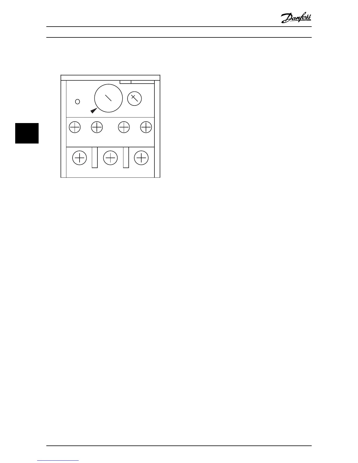
Illustration 5.5 Sample Overload Device
5.1.6
EMB Safety Interlock
General information
The safety interlock feature prevents the drive or bypass
from operating. For operation in drive or bypass, the safety
interlock input contact must be closed. Only a fire mode
command to run in bypass overrides this function. Safety
inputs include, but are not limited to, high and low
pressure limit switches, fire alarm, smoke alarm, high and
low temperature switches, and vibration sensors.
Operation
When an external safety input closes, the option panel is in
operational mode. When open, power is interrupted to all
contactors and relays and the bypass ignores all run
commands except for fire mode operation, when enabled.
When power is interrupted in drive mode, the drive display
indicates an external fault, meaning the problem is
external to the drive. In some instances, a fault can be
caused by a failure within the option panel, which will still
be reported as an external fault from the drive. A factory
installed jumper allows the unit to operate when no safety
input is connected. This jumper must be removed when
connecting in a safety interlock circuit.
Safety interlock function setup
•
For EMB1 and EMB2, remove factory-installed
jumper between terminals 5 and 6 on connector
X55.
•
Wire safety input to terminals 5 and 6 on
connector X55.
•
For EMB(0), wire safety input to connector TB1,
terminals 1 and 2.
5.1.7
EMB Fire Mode
General Information
The fire mode function is built-in. Fire mode runs the
motor at full speed in bypass and is intended to ignore
common safety, overload, and bypass switch inputs in
emergency situations. The motor will continue to run in
bypass until fire mode is removed or the unit fails.
Before enabling fire mode
•
Complete the start-up procedure to verify motor
rotation direction in bypass is correct and that
the system is ready in all respects for continuous
full speed operation in bypass.
Operation
•
Activation of fire mode is accomplished by
closing connector X55, input terminals 7 and 8.
•
When activated, a relay overrides the safety
circuit, motor overload, and bypass switch (SW1)
position.
•
Fire mode is deactivated only when removed or
fuses blow.
•
Fire mode status can be reported through
connector X55, terminals 9 and 10, a normally
open dry contact that closes when fire mode is
active.
Fire mode function setup
•
Wire fire mode input to connector X55, terminals
7 and 8.
•
Wire fire mode status output to connector X55,
terminals 9 and 10.
5.1.8
EMB Fault Reporting
General information
A fault indication is provided if the drive experiences a
fault or bypass input power is lost. The EMB2 bypass
control card monitors the drive fault output for status
reporting. The fault contacts are fail-safe, meaning that if
power is removed a fault condition is automatically
reported. Fault status is not monitored in bypass
operation.
Operation
For the EMB2, fault reporting is monitored through a
Form-C relay (RL2) on the bypass control board. The relay
reports a fault on connector X56 terminals 7, 8, and 9. In
normal operation, the relay is powered and terminal 7 is
closed with terminal 9 open. In a fault condition, power to
the relay is lost and the relay positions automatically
reverse, signaling the fault condition. Terminal 8 is the
common to both. For the EMB(0) or EMB1, drive terminals
1 (common), 2 and 3 report faults with 2 open and 3
closed in the fault condition.
Electromechanical Bypass (E... Option Panel Operating Instructions
40 MG14I102 - VLT
®
is a registered Danfoss trademark
55
 Loading...