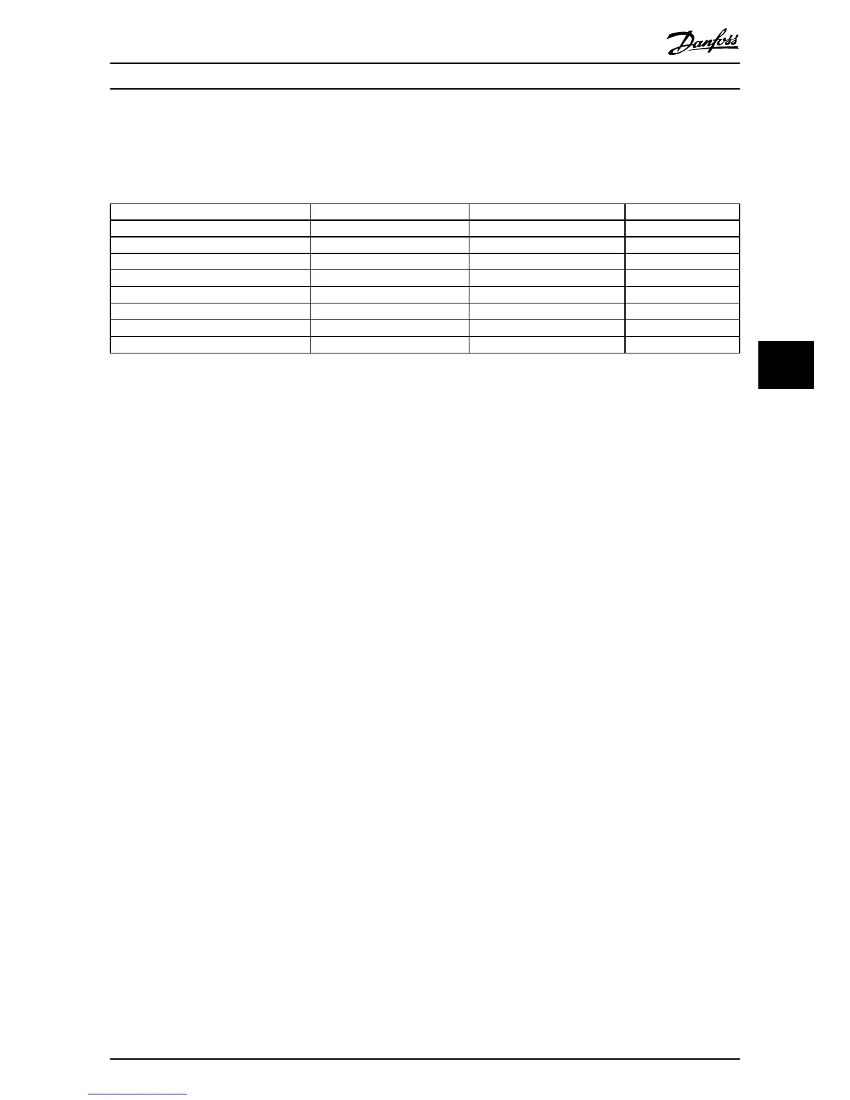
Terminal functions are programmed in parameter group 5-
** Digital In/Out. (See Table 6.2 for factory default
parameter settings for drives with an ECB). Bypass
functions are programmed in parameter group 31-**
Bypass Option (see 6.1.7 ECB Mode of Operation). See the
drive’s supporting materials for detailed programming
instructions.
Parameter Setting title Setting Function
5-01 Terminal 27 Mode Input 0 Customer Interlock
5-02 Terminal 29 Mode Output 1 Auto bypass
5-10 Terminal 18 Digital Input Start 8 Common run/stop
5-11 Terminal 19 Digital Input Run Permissive 52 Run Permissive
5-12 Terminal 27 Digital Input External Interlock 7 Customer Interlock
5-31 Terminal 29 Digital Output No Alarm 160 Auto bypass
5-40 Function Relay (0) Start Command Active 167 Run Permissive
5-40 Function Relay (0) Off Delay 0.00 S Run Permissive
Table 6.2 Parameter Group 5-** Digital In/Out Factory Default Settings
Electronically Controlled B... Option Panel Operating Instructions
MG14I102 - VLT
®
is a registered Danfoss trademark 43
6
6