VLT
®
FCD Series
■ Dynamic braking
With the FCD 300 the dynamic braking quality in an
application can be improved in two ways, either with
the aid of brake resistors or AC braking.
Danfoss offers a complete range of brake resistors
for all FCD 300 frequency converters.
It is the job of the brake resistor to apply a load to
the intermediate circuit during braking, thereby en-
suring that the brake power can be absorbed by the
brake resistor.
Without a brake resistor, the intermediate circuit volt-
age of the frequency converter would go on rising,
until cutting out for protection. The advantage of us-
ing a brake resistor is that you can brake quickly with
large loads, e.g. on a conveyor belt.
Danfoss has chosen a solution in which the brake
resistor is not integrated into the frequency con-
verter. This gives the user the following advantages:
- The resistor’s cycle time can be selected as re-
quired.
- The heat generated during braking can be
diverted outside the panel cabinet, where the en-
ergy can possibly be utilised.
- No overheating of the electronic components,
even if the brake resistor is overloaded.
An internal brake resistorcan be mounted on the
small brake duty cycles.
AC braking is an integrated function that is used for
applications in which there is a need for limited dy-
namic braking. The AC braking function makes it
possible to reduce the brake power in the motor in-
stead of in a brake resistor. The function is intended
for applications where the required braking torque is
less than 50% of rated torque. AC braking is se-
lected in par. 400 Brake function.
NB!:
The AC brake cannot be used if the required
braking torque is more than 50% of rated
braking torque. In such instances a brake resistor
must be used.
■ Brake Setup
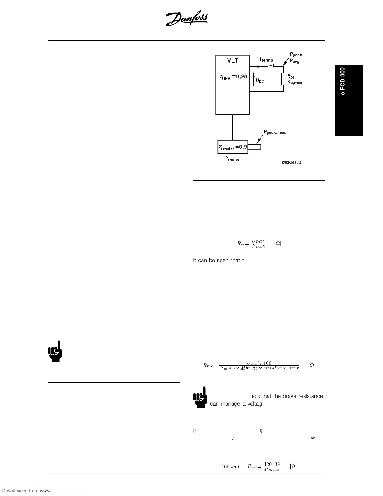
The figure shows a brake Setup with a frequency
converter.
In the following paragraphs, expressions and
acronyms are used about brake Setups that can be
seen from the figure.
■ Calculation of brake resistance
To ensure that the frequency converter does not cut
out for safety reasons when the motor brakes, the
resistance value is selected on the basis of the peak
braking effect and the intermediate circuit voltage:
R
br
=
U
DC
2
P
peak
[]
It can be seen that the brake resistance depends on
the intermediate circuit voltage (UDC).
With frequency converters that have a mains voltage
of 3 x 380 - 480 Volt, the brake will be active at 770
Volt (UDC).
You can also choose to use the brake resistance
recommended by Danfoss (R
REC
). This is a guaran-
tee that the frequency converter is able to brake at
the highest braking torque (M
BR
). The recommended
brake resistance can be seen from the ordering table
for brake resistors.
R
REC
calculated as:
R
rec
=
U
DC
2
2
100
P
motor
2
Mbr
(%)
2
motor
2
inv
[]
NB!:
Remember to check that the brake resistance
can manage a voltage of 850 Volt or 430 Volt,
if Danfoss brake resistors are not being used.
motor
is typically 0.90 and
INV
is typically 0.98. For
400 Volt, R
REC
at 160% braking torque can be writ-
ten as:
400
volt R
rec
=
420139
P
motor
[]
MG.04.A1.02 - VLT is a registered Danfoss trade mark
17
Introduction to FCD 300
 Loading...


