VLT
®
FCM Series
Programming
Example:
Parameter 201: minimum frequency, conversion factor
0,1. If parameter 201 is to be set to 10 Hz, a value of
100 must be transferred, since a conversion factor of
0,1 means that the transferred value will be multiplied
by 0.1. A value of 100 will thus be understood as 10.
A
ddressing by unit ID
The unit ID is printed on the label on the plastic
cover under the lid of the electronics box. The three
groups of unit ID each with three digits must be
converted to Hex. The desired address is added as
the last byte. The frame is sent to the bus address
parameter(s) 500 (and 918) via a broadcast.
PKE: Write to parameter No. 500 or 918
IND: Not Used
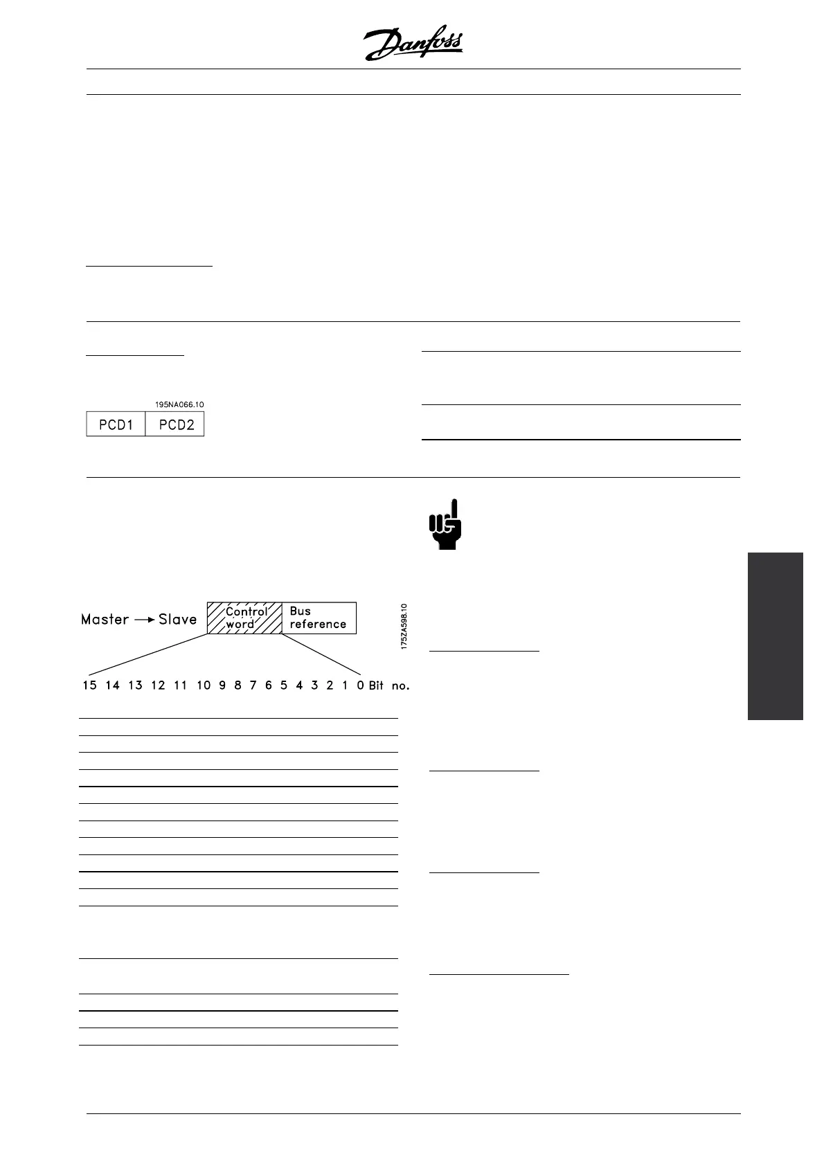
2. Process-bytes
The process byte block is divided into two blocks each
of 16 bits, which always come in the sequence stated.
PCD1 PCD2
Control
telegram
(master→slave)
Control word Reference
value
Reply telegram
(slave→master)
Status word Given output
frequency
■ Control wordaccording to FieldbusProfile Standard
(parameter 512 = Fieldbus Profile) The control word
is used for transmitting commands from a master
(e.g. a PC) to a slave (FC motor).
Bit Bit = 0 Bit =1
00 OFF 1 ON 1
01 OFF 2 ON 2
02 OFF 3 ON 3
03 Motor coasting Enable
04 Quick-stop Ramp
05 Freeze output frequency Ramp enable
06 Ramp stop Start
07 No function Reset
08 Jog1OFF ON
09 Jog2OFF ON
10 Data not valid Valid
11 No function Slow down /
Relay 123 / Digital
output terminal 9
12 No function Catch-up / Relay
123
13 Setup 1 Setup 2
14
15 No function Reversing
NB!:
The use of Bit 00, Bit 01 and Bit 02 for
switching off the power supply (by use of
relay) will require a separate power on. This
because there is no 24V external connection to supply
the FCM 300 control, which is required to activate
the FCM 300 again via input signal.
B
it 00, OFF1/ON1:
An ordinary ramp stop which uses the ramp time
in parameters 207/208. Bit 00 = "0" leads to
a stop. Bit 00 = "1" means that the frequency
converter will be able to start if the other conditions
for starting have been fulfilled.
B
it 01, OFF2/ON2:
Coasting stop. Bit 01 = "0" leads to a coasting stop.
Bit 01 = "1" means that the frequency converter
is able to start, provided the other conditions
for starting have been fulfilled.
B
it 02, OFF3/ON3:
Quick-stop, which uses the ramp time in parameter 212.
Bit 02 = "0" leads to a quick-stop. Bit 02 = "1" means
that the frequency converter is able to start, provided
the other conditions for starting have been fulfilled.
B
it 03, Coasting/enable:
Coasting. Bit 03 = "0" leads to a stop. Bit 03 =
"1" means that the frequency converter is able to
start, provided the other conditions for starting are
fulfilled. Note: In parameter 502 the choice is made
MG.03.H3.02 - VLT is a registered Danfoss trademark
81
 Loading...


