Mounting
To adapt to the mounting holes of FC 280, contact the
local Danfoss supplier to order a separate backplate.
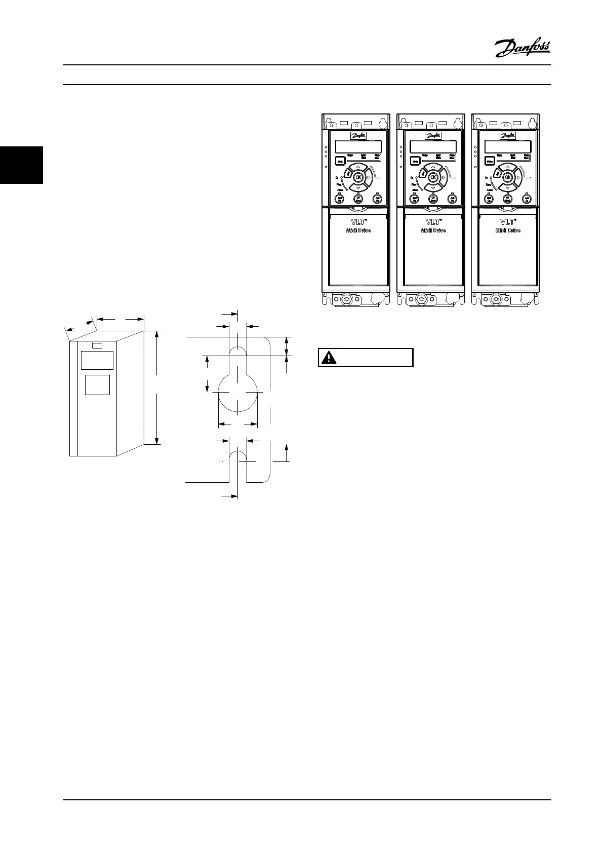
To mount the adjustable frequency drive:
1. Ensure that the strength of the mounting location
supports the unit weight. The adjustable
frequency drive allows side-by-side installation.
2. Locate the unit as close to the motor as possible.
Keep the motor cables as short as possible.
3. Mount the unit vertically to a solid at surface or
to the optional backplate to provide cooling
airow.
4. When provided, use the slotted mounting holes
on the unit for wall mounting.
Figure 3.2 Top and Bottom Mounting Holes (See
chapter 9.9 Enclosure Sizes, Power Ratings and Dimensions)
3.3.1 Side-by-side Installation
Side-by-side installation
All FC 280 units can be installed side-by-side in vertical or
horizontal position. The units do not require extra
ventilation on the side.
Figure 3.3 Side-by-side Installation
CAUTION
RISK OF OVERHEATING
If IP21 solution is used, mounting the units side-by-side
could lead to overheating and unit damages.
•
Avoid mounting the units side-by-side if IP21
solution is used.
3.3.2 Bus Decoupling Kit
The bus decoupling kit ensures mechanical xation and
electrical shielding of cables for the following control
cassette variants:
•
Control cassette with PROFIBUS.
•
Control cassette with PROFINET.
•
Control cassette with CANopen.
•
Control cassette with Ethernet.
Each bus decoupling kit contains one horizontal
decoupling plate and one vertical decoupling plate.
Mounting the vertical decoupling plate is optional. The
vertical decoupling plate provides better mechanical
support for PROFINET and Ethernet connectors and cables.
3.3.3 Mounting
To mount the bus decoupling kit:
1. Place the horizontal decoupling plate on the
control cassette that is mounted on the
adjustable frequency drive, and fasten the plate
Mechanical Installation
VLT
®
Midi Drive FC 280
8 Danfoss A/S © 11/2015 All rights reserved. MG07A122
33
 Loading...


