3 Mechanical Installation
3.1 Unpacking
3.1.1 Items Supplied
Items supplied may vary according to product congu-
ration.
•
Make sure the items supplied and the information
on the nameplate correspond to the order conr-
mation.
•
Check the packaging and the adjustable
frequency drive visually for damage caused by
inappropriate handling during shipment. File any
claim for damage with the carrier. Retain
damaged parts for clarication.
130BE616.11
V LT
MADE BY DANFOSS IN CHINA
T/C: FC-280PK55T4E20H1BXCXXXSXXXXA6
0.55kW 0.75HP
IN: 3x380-480V 50/60Hz, 1.6/1.3A
Functional
Safety
Type
Approved
OUT: 3x0-Vin 0-500Hz, 1.7/1.6A (Tamb. 45˚C)
Enclosure: CHASSIS/IP20
P/N: 134U2993 S/N: 000000G000
Midi Drive
www.danfoss.com
CAUTION:
WARNING:
SEE MANUAL
76X1 E134261 Ind.contr.Eq. See manual for prefuse
STORED CHARGE DO NOT TOUCH UNTILL 4 MIN. AFTER
DISCONNECTION
RISK OF ELECTRIC SHOCK-DUAL SUPPLY DISCONNECT MAINS
AND LOADSHARING BEFORE SERVICE
1
7
10
9
8
2
3
4
6
11
5
www.tuv.com
ID 1234567890
R
US LISTED
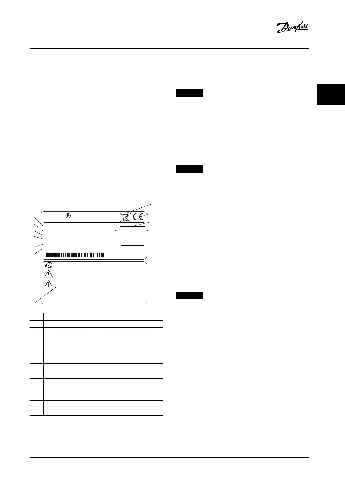
1 Type code
2 Order number
3 Power rating
4
Input voltage, frequency and current (at low/high
voltages)
5
Output voltage, frequency and current (at low/high
voltages)
6 Enclosure type and IP rating
7 Disposal
8 CE mark
9 Serial number
10 Functional safety
11 Rated ambient temperature
12 Discharge time (Warning)
Figure 3.1 Product Nameplate (Example)
NOTICE!
Do not remove the nameplate from the adjustable
frequency drive (loss of warranty).
3.1.2 Storage
Ensure that requirements for storage are fullled. Refer to
chapter 9.4 Ambient Conditions for further details.
3.2 Installation Environment
NOTICE!
In environments with airborne liquids, particles or
corrosive gases, ensure that the IP/Type rating of the
equipment matches the installation environment. Failure
to meet requirements for ambient conditions can reduce
lifetime of the adjustable frequency drive. Ensure that
requirements for air humidity, temperature and altitude
are met.
Vibration and shock
The adjustable frequency drive complies with requirements
for units mounted on the walls and oors of production
premises, as well as in panels bolted to walls or oors.
For detailed ambient conditions specications, refer to
chapter 9.4 Ambient Conditions.
3.3
Mounting
NOTICE!
Improper mounting can result in overheating and
reduced performance.
Cooling
•
Ensure 100 mm (4 in) of top and bottom
clearance for air cooling.
Lifting
•
To determine a safe lifting method, check the
weight of the unit, see chapter 9.9 Enclosure Sizes,
Power Ratings and Dimensions.
•
Ensure that the lifting device is suitable for the
task.
•
If necessary, plan for a hoist, crane or forklift with
the appropriate rating to move the unit.
•
For lifting, use hoist rings on the unit, when
provided.
Mechanical Installation Instruction Manual
MG07A122 Danfoss A/S © 11/2015 All rights reserved. 7
3 3
 Loading...


