8.4 List of Warnings and Alarms
An (X) marked in Table 8.1 indicates that the warning or alarm has occurred.
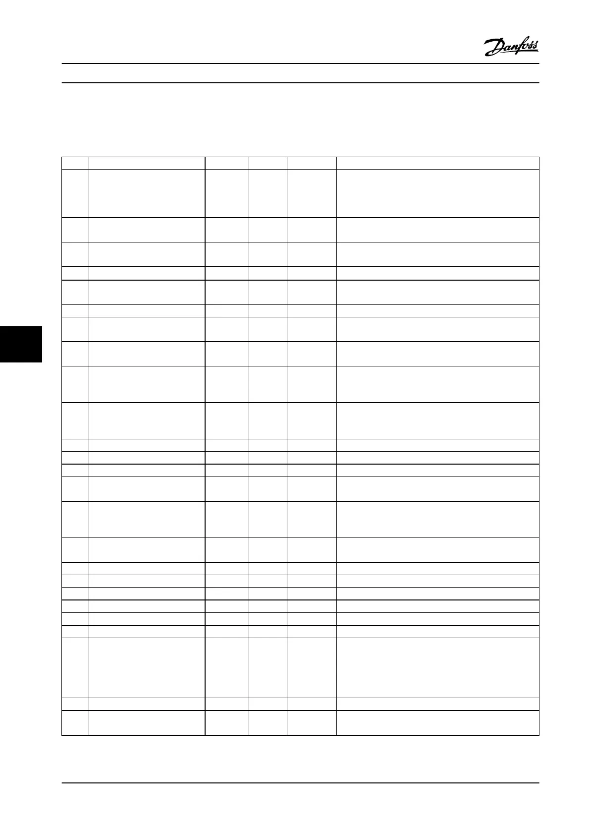
No. Description Warning Alarm Trip lock Cause
2 Live zero error X X –
Signal on terminal 53 or 54 is less than 50% of value set
in parameter 6-10 Terminal 53 Low Voltage,
parameter 6-20 Terminal 54 Low Voltage and
parameter 6-22 Terminal 54 Low Current.
3 No motor X – –
No motor has been connected to the output of the
adjustable frequency drive.
4 Mains phase loss1) X X X
Missing phase on supply side, or the voltage imbalance is
too high. Check the supply voltage.
7
DC overvoltage
1)
X X –
DC link voltage exceeds limit.
8
DC undervoltage
1)
X X –
DC link voltage drops below the voltage warning low
limit.
9 Inverter overloaded X X – More than 100% load for too long.
10 Motor ETR overtemperature X X –
Motor is too hot due to more than 100% load for too
long.
11
Motor thermistor overtem-
perature
X X –
Thermistor or thermistor connection is disconnected, or
the motor is too hot.
12 Torque limit X X –
Torque exceeds value set in either parameter 4-16 Torque
Limit Motor Mode or parameter 4-17 Torque Limit Generator
Mode.
13 Overcurrent
X X X
Inverter peak current limit is exceeded. If this alarm
occurs on power-up, check whether power cables are
mistakenly connected to the motor terminals.
14 Ground fault X X X Discharge from output phases to ground.
16 Short circuit X X Short circuit in motor or on motor terminals.
17 Control word timeout X X No communication to the adjustable frequency drive.
25 Brake resistor short-circuited – X X
Brake resistor is short circuited, thus the brake function is
disconnected.
26 Brake overload X X –
The power transmitted to the brake resistor over the last
120 s exceeds the limit. Possible corrections: Decrease
brake energy via lower speed or longer ramp time.
27
Brake IGBT/Brake chopper short
circuited
– X X
Brake transistor is short-circuited, thus the brake function
is disconnected.
28 Brake check – X Brake resistor is not connected/working.
30 U phase loss – X X Motor phase U is missing. Check the phase.
31 V phase loss – X X Motor phase V is missing. Check the phase.
32 W phase loss – X X Motor phase W is missing. Check the phase.
34 Fieldbus fault X X – PROFIBUS communication issues have occurred.
35 Option fault – X – Serial communication bus detects internal errors.
36 Mains failure X X –
This warning/alarm is only active if the supply voltage to
the adjustable frequency drive is less than the value set
in parameter 14-11 Mains Voltage at Mains Fault, and
parameter 14-10 Mains Failure is NOT set to [0] No
Function.
38 Internal fault – X X Contact the local Danfoss supplier.
40 Overload T27 X – –
Check the load connected to terminal 27 or remove short
circuit connection.
Maintenance, Diagnostics an...
VLT
®
Midi Drive FC 280
44 Danfoss A/S © 11/2015 All rights reserved. MG07A122
88
 Loading...


