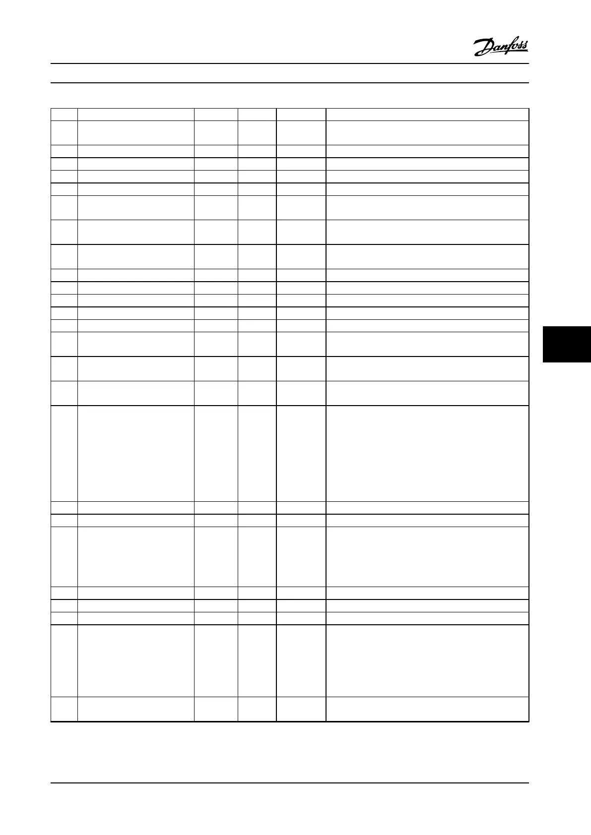
No. Description Warning Alarm Trip lock Cause
41 Overload T29 – – –
Check the load connected to terminal 29 or remove short
circuit connection.
46 Gate drive voltage fault X X
47 24 V supply low X X X 24 V DC may be overloaded.
51 AMA check U
nom
and I
nom
– X – Wrong setting for motor voltage and/or motor current.
52 AMA low I
nom
– X – Motor current is too low. Check the settings.
53 AMA big motor
– X –
The power size of the motor is too large for the AMA to
operate.
54 AMA small motor
– X –
The power size of the motor is too small for the AMA to
operate.
55 AMA parameter range – X –
The parameter values of the motor are outside of the
acceptable range. AMA does not run.
56 AMA interrupt – X – The AMA is interrupted.
57 AMA timeout – X –
58 AMA internal – X – Contact Danfoss.
59 Current limit X X – Adjustable frequency drive overload.
61 Encoder loss X X –
63 Mechanical brake low – X –
Actual motor current has not exceeded release brake
current within start delay time window.
65 Control card temp
X X X
The cut-out temperature of the control card is 80 °C
(176 °F).
67 Option change
– X –
A new option is detected or a mounted option is
removed.
68 Safe Stop
X X –
STO is activated. If STO is in manual restart mode
(default), to resume normal operation, apply 24 V DC to
terminals 37 and 38 and initiate a reset signal (via serial
communication bus, digital I/O or [Reset]/[O Reset] key).
If STO is in automatic restart mode, applying 24 V DC to
terminals 37 an 38 automatically resumes the adjustable
frequency drive to normal operation. Refer to
chapter 6.3 STO Commissioning for more details.
69 Power card temp X X X
80 Drive initialized to default value X All parameter settings are initialized to default settings.
87 Auto DC braking X – –
Occurs in IT line power when the adjustable frequency
drive coasts and the DC voltage is higher than 830 V for
400 V units, and 425 V for 200 V units. Energy on DC link
is consumed by the motor. This function can be enabled/
disabled in parameter 0-07 Auto DC Braking.
88 Option detection – X X The option is removed successfully.
95 Broken belt X X –
120 Position control fault – X –
188 STO internal fault
– X –
24 V DC supply is connected to only one of the 2 STO
terminals (37 and 38), or a failure in STO channels is
detected. Make sure that both terminals are connected to
24 V DC supply, and the discrepancy between the signals
at the two terminals is less than 12 ms. If the fault still
occurs, contact the local Danfoss supplier.
nw
run
Not while running – – –
Parameter can only be changed when the motor is
stopped.
Maintenance, Diagnostics an... Instruction Manual
MG07A122 Danfoss A/S © 11/2015 All rights reserved. 45
8 8
 Loading...


