130BD391.11
1
2
3
4
5
6
78
9
10
Reset
Auto
On
Hand
On
OK
Back
Menu
Status Quick
Menu
Main
Menu
PE
U
V
W
L1
L2
L3
PE
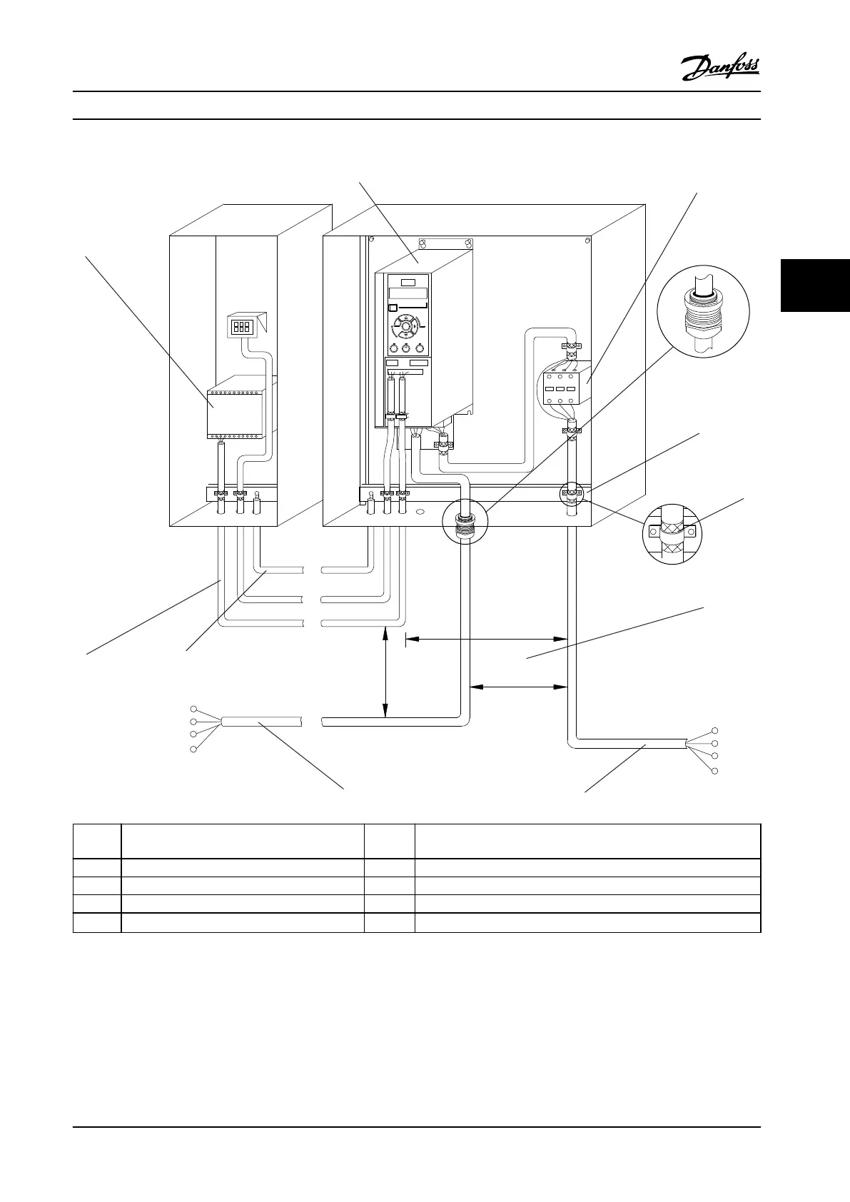
1 PLC 6 Minimum 200 mm (7.9 in) between control cables, motor and line
power.
2 Adjustable frequency drive 7 Motor, 3-phase and PE
3 Output contactor (generally not recommended) 8 Line power, single-phase, 3-phase and reinforced PE
4 Grounding rail (PE) 9 Control wiring
5 Cable shielding (stripped) 10
Equalizing minimum 16 mm
2
(6 AWG)
Figure 4.3 Typical Electrical Connection
Electrical Installation Instruction Manual
MG07A122 Danfoss A/S © 11/2015 All rights reserved. 13
4 4
 Loading...


