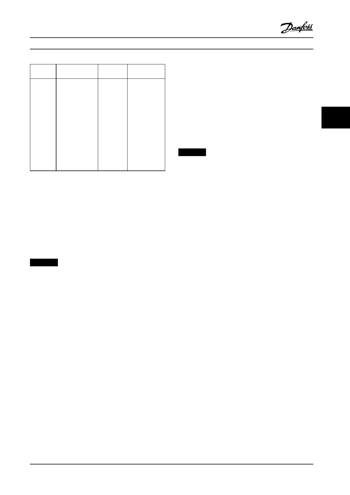
Terminal Parameter
Default
setting
Description
01, 02, 03 5-40 [9] Alarm
Form C relay
output. These
relays are in
various locations
depending upon
the adjustable
frequency drive
conguration
and size. Usable
for AC or DC
voltage and
resistive or
inductive loads.
Table 4.2 Terminal Descriptions - Serial Communication
4.8.2 Wiring to Control Terminals
Control terminal connectors can be unplugged from the
adjustable frequency drive for ease of installation, as
shown in Figure 4.8.
For details about STO wiring, refer to chapter 6 Safe Torque
O (STO).
NOTICE!
Keep control cables as short as possible and separate
them from high power cables to minimize interference.
1. Loosen the screws for the terminals.
2. Insert sleeved control cables into the slots.
3. Fasten the screws for the terminals.
4. Ensure that the contact is rmly established and
not loose. Loose control wiring can be the source
of equipment faults or less than optimal
operation.
See chapter 9.5 Cable Specications for control terminal
cable sizes and chapter 7 Application Examples for typical
control cable connections.
4.8.3 Enabling Motor Operation
(Terminal 27)
A jumper wire is required between terminal 12 (or 13) and
terminal 27 for the adjustable frequency drive to operate
when using factory default programming values.
•
Digital input terminal 27 is designed to receive 24
V DC external interlock command.
•
When no interlock device is used, wire a jumper
between control terminal 12 (recommended) or
13 to terminal 27. The jumper provides an
internal 24 V signal on terminal 27.
•
Only for GLCP: When the status line at the
bottom of the LCP reads AUTO REMOTE COAST, it
indicates that the unit is ready to operate but is
missing an input signal on terminal 27.
NOTICE!
UNABLE TO START
The adjustable frequency drive cannot operate without a
signal on terminal 27, unless terminal 27 is reprog-
rammed.
4.8.4 Mechanical Brake Control
In hoisting/lowering applications, it is necessary to
control an electro-mechanical brake.
•
Control the brake using any relay output or
digital output (terminal 27).
•
Keep the output closed (voltage-free) as long as
the adjustable frequency drive is unable to keep
the motor at standstill, for example, due to the
load being too heavy.
•
Select [32] Mechanical brake control in parameter
group 5-4* Relays for applications with an electro-
mechanical brake.
•
The brake is released when the motor current
exceeds the preset value in
parameter 2-20 Release Brake Current.
•
The brake is engaged when the output frequency
is less than the frequency set in
parameter 2-22 Activate Brake Speed [Hz], and only
if the adjustable frequency drive carries out a
stop command.
If the adjustable frequency drive is in alarm mode or in an
overvoltage situation, the mechanical brake immediately
closes.
The adjustable frequency drive is not a safety device. It is
the responsibility of the system designer to integrate safety
devices according to relevant national crane/lift
regulations.
Electrical Installation Instruction Manual
MG07A122 Danfoss A/S © 11/2015 All rights reserved. 17
4 4
 Loading...


