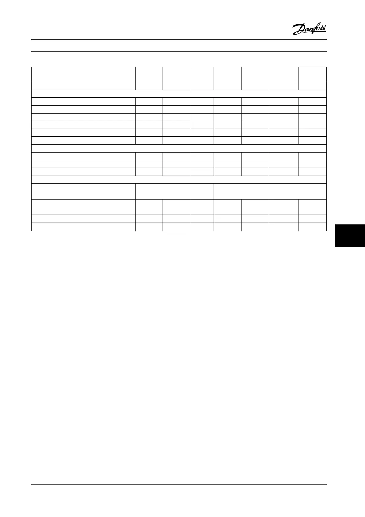
Adjustable frequency driver
typical shaft output [kW] (hp)
H4K0
4 (5)
H5K5
5.5 (7.5)
H7K5
7.5 (10)
H11K
11 (15)
H15K
15 (20)
H18K
18.5 (25)
H22K
22 (30)
IP20 K2 K2 K3 K4 K4 K5 K5
Output current
Shaft output [kW] (hp) 4 (5) 5.5 (7.5) 7.5 (10) 11 (15) 15 (20) 18.5 (25) 22 (30)
Continuous (3x380–440 V) [A] 9 12 15.5 23 31 37 42.5
Continuous (3x441–480 V) [A] 8.2 11 14 21 27 34 40
Intermittent (60 s overload) [A] 14.4 19.2 24.8 34.5 46.5 55.5 63.8
Continuous kVA (400 V AC) [kVA] 6.24 8.32 10.74 15.94 21.48 25.64 29.45
Continuous kVA (480 V AC) [kVA] 6.8 9.1 11.6 17.5 22.4 28.3 33.3
Maximum input current
Continuous (3x380–440 V) [A] 8.3 11.2 15.1 22.1 29.9 35.2 41.5
Continuous (3x441–480 V) [A] 6.8 9.4 12.6 18.4 24.7 29.3 34.6
Intermittent (60 s overload) [A] 13.3 17.9 24.2 33.2 44.9 52.8 62.3
Additional specications
Maximum cable size (line power, motor, brake)
[mm
2
(AWG)]
4(12) 16(6)
Estimated power loss at rated maximum load
[W]
1)
115.5 157.54 192.83 289.53 393.36 402.83 467.52
Weight enclosure IP20 [kg] (hp) 3.6 (7.94) 3.6 (7.94) 4.1 (9.04) 9.4 (20.7) 9.5 (20.94) 12.3 (27.12) 12.5 (27.6)
Eciency [%]
2)
97.6 97.7 98.0 97.8 97.8 98.1 97.9
Table 9.2 Line Power Supply 3x380–480 V AC
1) The typical power loss is at nominal load conditions and expected to be within
±
15% (tolerance relates to variances in voltage and
cable conditions).
Values are based on a typical motor eciency (IE2/IE3 border line). Motors with lower eciency add to the power loss in the adjustable
frequency drive and motors with high eciency reduce power loss.
Applies for dimensioning of adjustable frequency drive cooling. If the switching frequency is higher than the default setting, the power
losses may rise. LCP and typical control card power consumptions are included. Further options and customer load may add up to 30 W
to the losses (though typical only 4 W extra for a fully loaded control card or serial communication bus).
For power loss data according to EN 50598-2, refer to www.danfoss.com/vltenergyeciency.
2) Measured using 50 m (165 ft) shielded motor cables at rated load and rated frequency. For energy eciency class, see
chapter 9.4 Ambient Conditions. For part load losses, see www.danfoss.com/vltenergyeciency.
Specications Instruction Manual
MG07A122 Danfoss A/S © 11/2015 All rights reserved. 49
9 9
 Loading...


