Analog inputs
Number of analog inputs 2
Terminal number 53
1)
, 54
Modes Voltage or current
Mode select Software
Voltage level 0–10 V
Input resistance, R
i
approximately 10 kΩ
Maximum voltage -15 V to +20 V
Current level 0/4 to 20 mA (scaleable)
Input resistance, R
i
approximately 200 Ω
Maximum current 30 mA
Resolution for analog inputs 11 bit
Accuracy of analog inputs Maximum error 0.5% of full scale
Bandwidth 100 Hz
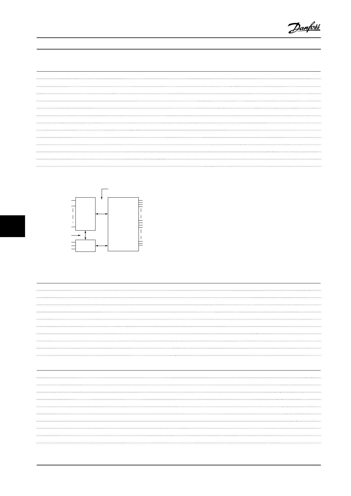
The analog inputs are galvanically isolated from the supply voltage (PELV) and other high-voltage terminals.
1) Terminal 53 supports only voltage mode and can also be used as digital input.
Mains
Functional
isolation
PELV isolation
Motor
DC Bus
High
voltage
Control
+24 V
RS-485
18
31
130BD310.10
Figure 9.1 Analog Inputs
Pulse inputs
Programmable pulse inputs 2
Terminal number pulse 29, 33
Maximum frequency at terminal 29, 33 32 kHz (push-pull driven)
Maximum frequency at terminal 29, 33 5 kHz (open collector)
Minimum frequency at terminal 29, 33 4 Hz
Voltage level See the section on digital input.
Maximum voltage on input 28 V DC
Input resistance, R
i
Approximately 4 kΩ
Pulse input accuracy (0.1–1 kHz) Maximum error: 0.1% of full scale
Pulse input accuracy (1–32 kHz) Maximum error: 0.05% of full scale
Digital outputs
Programmable digital/pulse outputs 1
Terminal number 27
Voltage level at digital/frequency output 0–24 V
Maximum output current (sink or source) 40 mA
Maximum load at frequency output 1 kΩ
Maximum capacitive load at frequency output 10 nF
Minimum output frequency at frequency output 4 Hz
Maximum output frequency at frequency output 32 kHz
Accuracy of frequency output Maximum error: 0.1% of full scale
Resolution of frequency output 10 bit
1) Terminal 27 can also be programmed as input.
Specications
VLT
®
Midi Drive FC 280
52 Danfoss A/S © 11/2015 All rights reserved. MG07A122
99
 Loading...


