Installation, use and maintenance manual
27
3.2 E
LECTRICAL INTERFACE
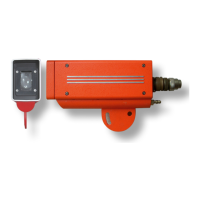
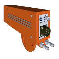
All the signals are reported to the 6-pole circular connector, MIL-C-5015 type, located on the rear side
of the photodetector.
We recommend cabling the signals of the connector to an intermediate junction box located near the
rolling line, easily accessed for inspection and maintenance. The junction box should represent the
connection point with the automation system.
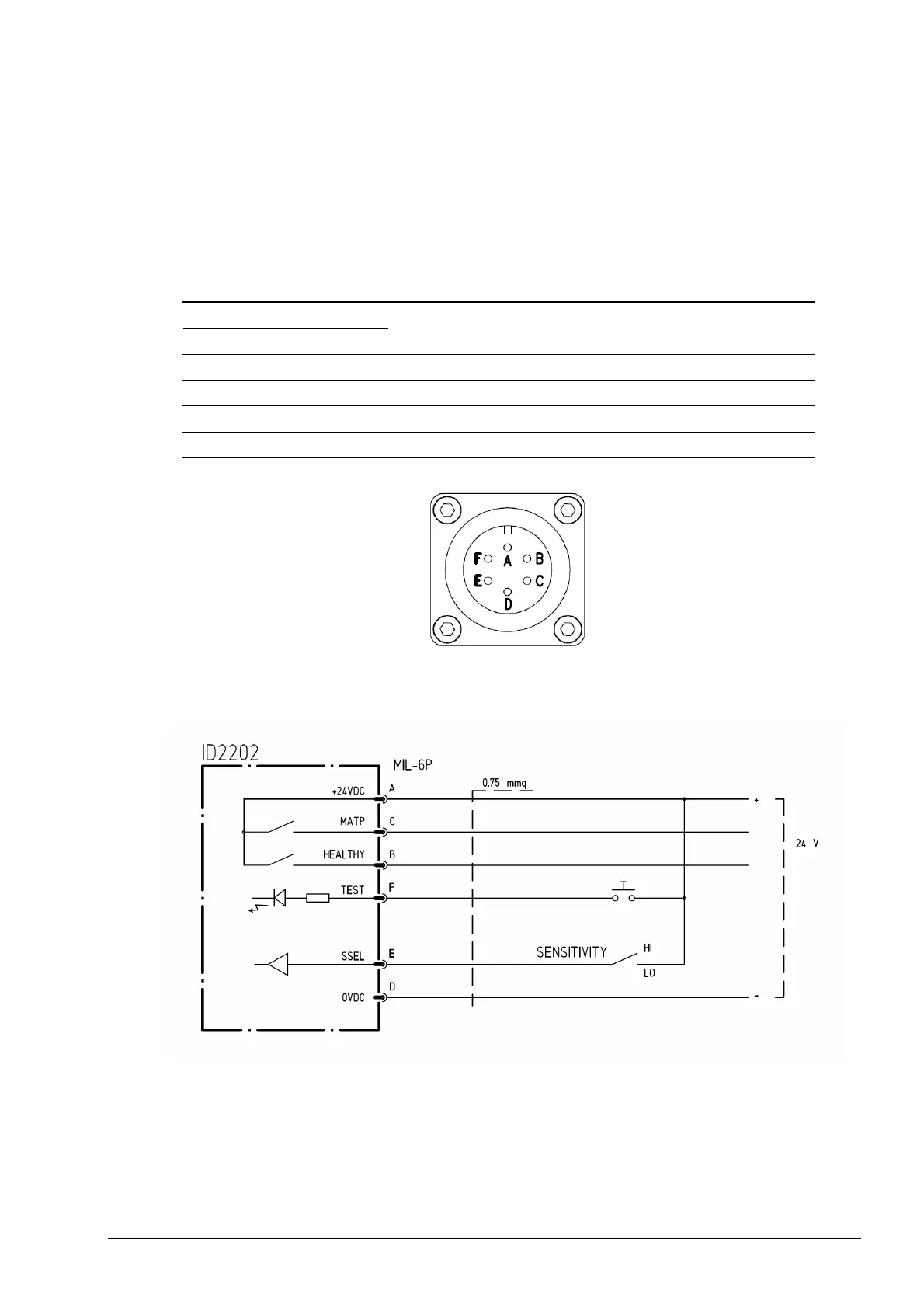
Pin Signal Function
A +24VDC
D 0VDC
Power input
C MATP Presence of material, digital output PNP
B HEALTHY Reliable detection, digital output PNP
F TEST Test, digital input
E SSEL Sensitivity selection, digital input
4. Circular connector
5.
Electrical connections
Danieli Automation Standard - Installation Use and Maintenance Manual - ID2202
Certified by OneDoc A.620.107 Rev.04-MU 28/145 #1061394
 Loading...