18
INSTALLATION & SERVICE MANUAL FOR PROFESSIONALS
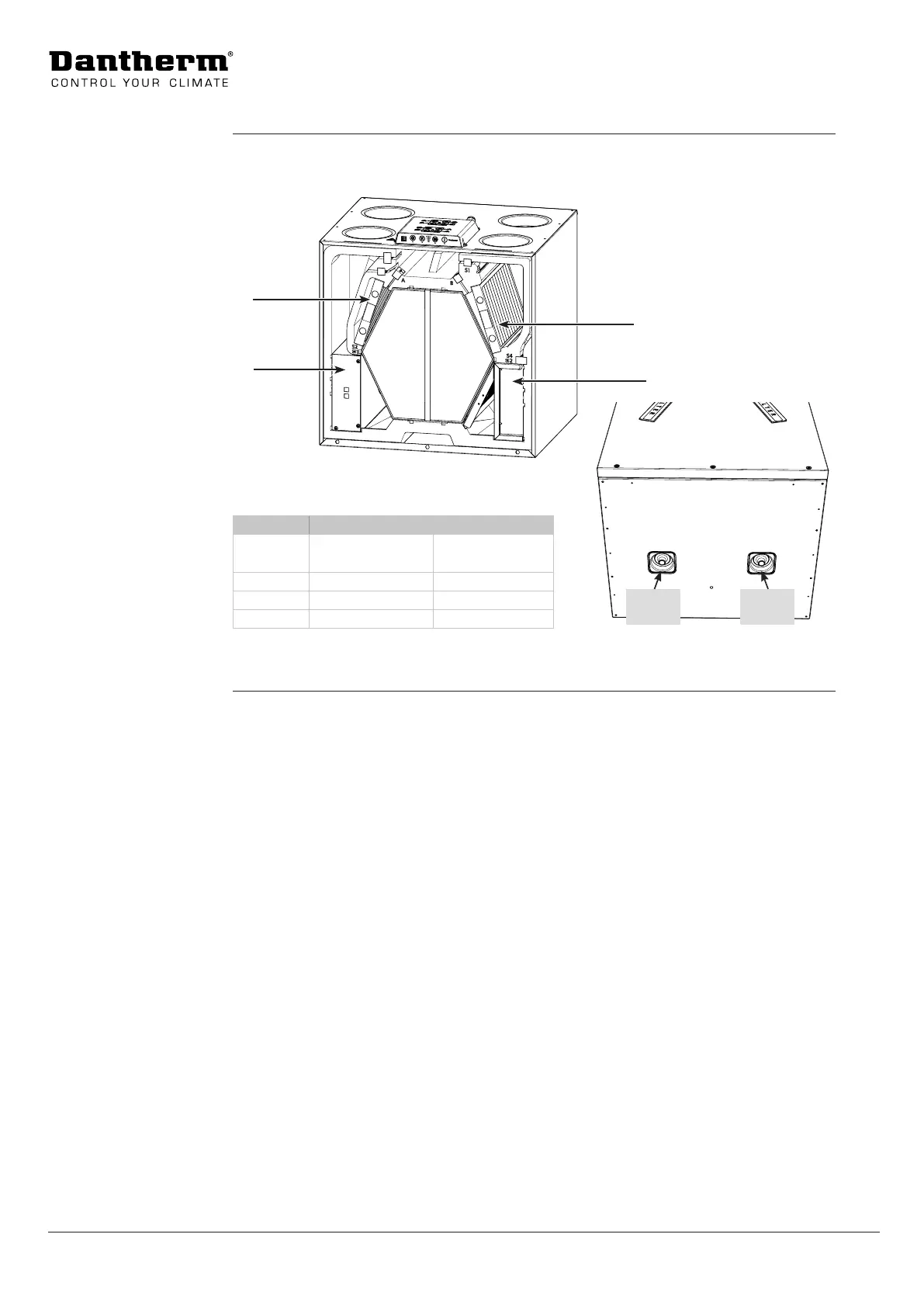
Product description: General description
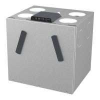
This illustration shows the function of the dierent parts in mode A/B, including the lter, fan
and use of drain outlet.
Filter 1
Fan box 2
Filter 2
Fan box 1
Fig. 5
Part Mode A Mode B
Filter 1 Exhaust air lter* Supply air lter**
Filter 2 Supply air lter** Exhaust air lter*
Fan box 2 Supply air fan Extract air fan
Fan box 1 Extract air fan Supply air fan
Fig. 6
* Exhaust air lter is an ISO Coarse 75% lter.
**Supply air lter can be either an ISO Coarse 75% standard lter or a ner ePM1>50% lter.
Description of
parts in mode A/B
Drain
mode B
Drain
mode A
 Loading...