Appendix J – General Purpose Input Output Port Applications
266 Class Series 2 Programmer’s Manual
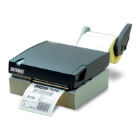
M-Class II GPIO
MII GPIO functions are detailed in the table below:
MII GPIO Overview
Pin
Number
Signal
Name
Signal
State
Signal
Direction*
Description
1 Vcc +5 VDC Output Printer: Max +5 VDC, 100mA
2
Printer
Fault
Low Output
Goes low upon printer detection of a fault
condition. Max +5 VDC, 100mA
3 Spare Reserved Input
Must be pulled high with 1k Ohm resistor
(see sample SOP circuit, below).
4
Start of
Print
(SOP)
Programmable Input
When active, will begin print. Recommend
only setting this signal to ACTIVE LOW.
When ready to print a label, the applicator
should hold this signal low for at least 50ms
– or until EOP goes not active. See sample
SOP circuit, below. Max +3.27 VDC, +/-
5mA
5
End of
Print
(EOP)
Programmable Output
Signifies the end of the print process. Can
be monitored to initiate next Start of Print
sequence. Minimum signal time 30ms. Max
+5 VDC, 100mA
6 & 8
Signal
Ground
Ground N/A Ground
7 +24 VDC 500mA Output Printer: Max +24 VDC, 500mA
[1]
Given relative to the printer.
[2]
Port operation is configuration dependent: Disable all unused optional functions (e.g., Present Sensor
or Cutter) and set GPIO to “YES” (or on display-equipped models, to APPLICATOR). Use the
Configuration Set command (<STX>Kc); or program the selections for non-display models via the
“Printer Setup Menu List” and for display-equipped models via the menu.
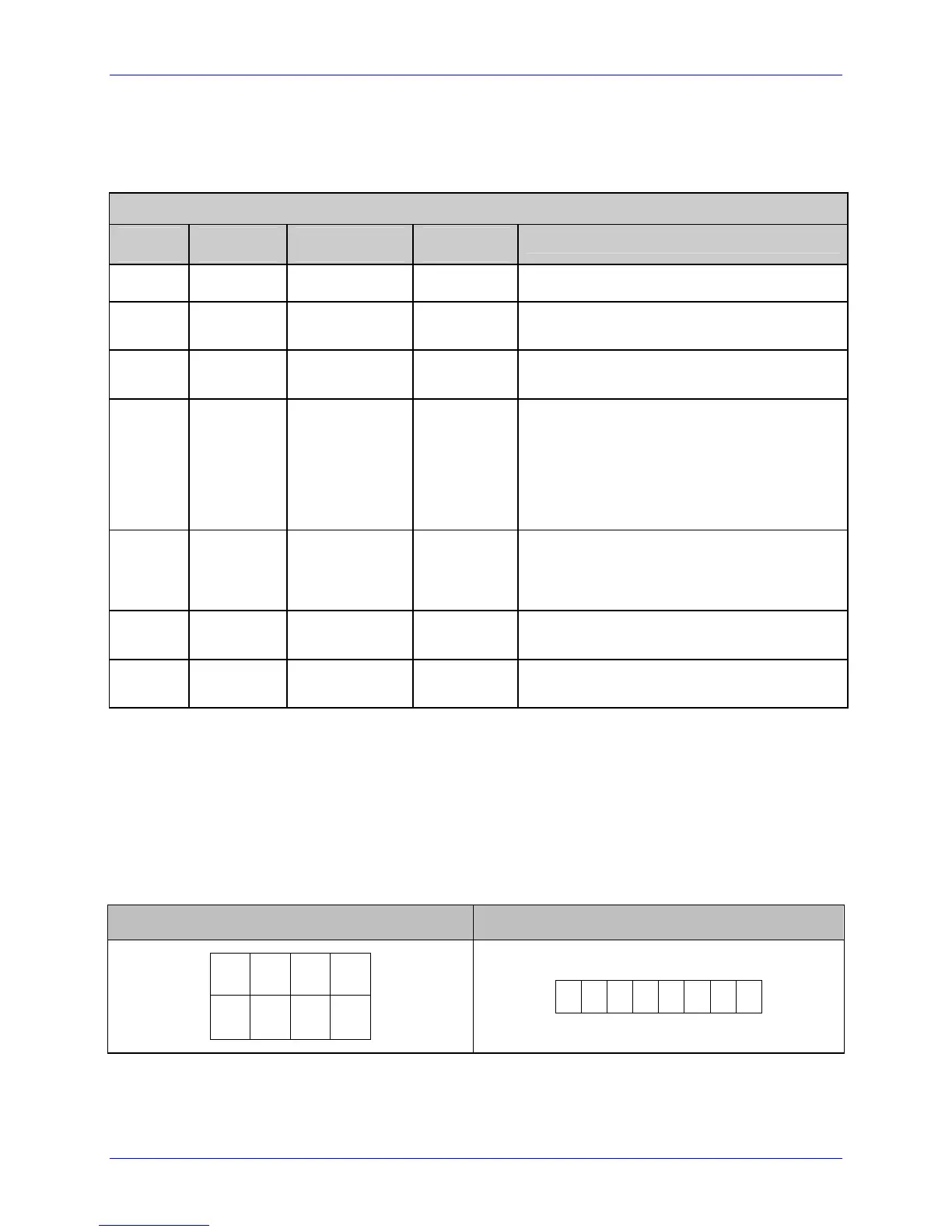
The GPIO signals can be accessed via the front Option Port connector (Molex, P/N 44300-
800), or via the Main PCB J6 connector (AMP, P/N 640456-8), where the pin-outs (as
viewed when facing the printer) are as follows:
Option Port Main PCB (J6)
8 6 4 2
7 5 3 1
1
2
3
4
5 6 7 8
 Loading...