Output
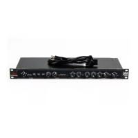
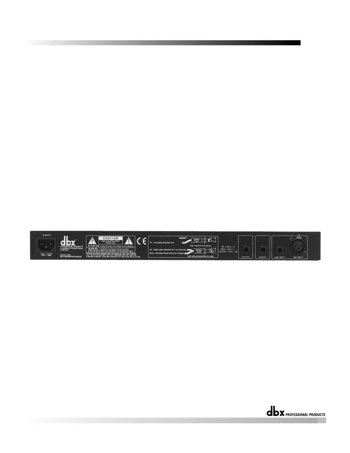
Rear Panel
percussion). Fairly low EXPANSION RATIO settings (and higher Expander/Gate
THRESHOLDs) work best for downward expansion, whereas higher EXPANSION
RATIO settings (clockwise towards 10:1) work best for gating. If a setting produces
undesirable “pumping” readjust the Expander/Gate EXPANSION RATIO and
THRESHOLD settings.
Note: The attack and release rate of the Expander/Gate are program-dependent -- very fast for transient
material (e.g., percussion) and slower for material with slow attack (e.g., vocals).
Readjust as needed to gate out noise -- external, as well as hiss from the unit. The
286A’s other processing can add substantial gain to a signal, especially at higher set-
tings, thereby increasing the noise floor.
GAIN (dB) Control and CLIP LED: The OUTPUT GAIN control sets the level at
the line output. The OUTPUT GAIN control is especially useful to compensate for
the RMS level changes which result from the 286A’s processing effects. For exam-
ple, to decrease the overall gain (e.g., when the 286A’s processing has added too
much gain), simply turn the OUTPUT GAIN control counterclockwise. The OUT-
PUT GAIN can also be used to counter any gain reduction after you have adjusted
the 286A’s controls for the desired amount of processing; adjust the OUTPUT GAIN
control clockwise, to add gain as needed.
The red OUTPUT GAIN LED (located to the right of the OUTPUT GAIN control)
lights when the 286A Processing Section is clipping; reduce gain via the OUTPUT
GAIN control. Set this control so that the OUTPUT CLIP LED never lights. If the
OUTPUT CLIP LED is still lit, reduce the gain caused by the 286A’s processors (e.g.,
high Compressor DRIVE settings) or the gain provided by an external processor con-
nected to the INSERT (if any).
If the meters on your load device (e.g., tape recorder, mixer, etc.) are in the red and
your OUTPUT CLIP LED is not lit, simply reduce the 286A’s OUTPUT GAIN until
the desired levels are obtained. If your load device is still in the red, reduce its input
attenuators (if available).
MIC INPUT Jack: The 286A’s MIC INPUT jack supports professional and home
studio microphones by accepting either balanced or unbalanced signal through an
XLR connector. Pins 2 and 3 are symmetrically balanced and floating; thus, either
can be used as “HOT” without difficulty. Pin 2 is in phase with the TIP of all 1/4”
connectors. Pin 1 is connected to the 286A’s chassis ground.
Note: Use a low impedance mic or a high-to-low impedance matching transformer with a high impedance
mic.
LINE INPUT Jack: Use a 1/4” TRS phone plug to connect line level sources to the
286A (e.g., mixer outputs, effects loops, electronic keyboards, etc.). The 286A’s
LINE INPUT jack accepts either balanced or unbalanced signals. Input impedance is
30kΩ unbalanced, 60kΩ balanced.
Note: In general, this jack does not support microphones with 1/4” plugs. Use an appropriate 1/4”-to-XLR
adapter and plug the microphone into the MIC INPUT jack.
5
 Loading...