Removing and Installing Parts 81
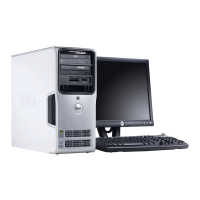
Drive Interface Connectors
Most interface connectors are keyed for correct insertion; that is, a notch or a missing pin on one
connector matches a tab or a filled-in hole on the other connector. Keyed connectors ensure that
the pin-1 wire in the cable (indicated by the colored stripe along one edge of the IDE cable—serial
ATA cables do not use a colored stripe) goes to the pin-1 end of the connector. The pin-1 end of a
connector on a board or a card is usually indicated by a silk-screened “1” printed directly on the
board or card.
NOTICE: When you connect an IDE interface cable, do not place the colored stripe away from pin 1 of
the connector. Reversing the cable prevents the drive from operating and could damage the controller,
the drive, or both.
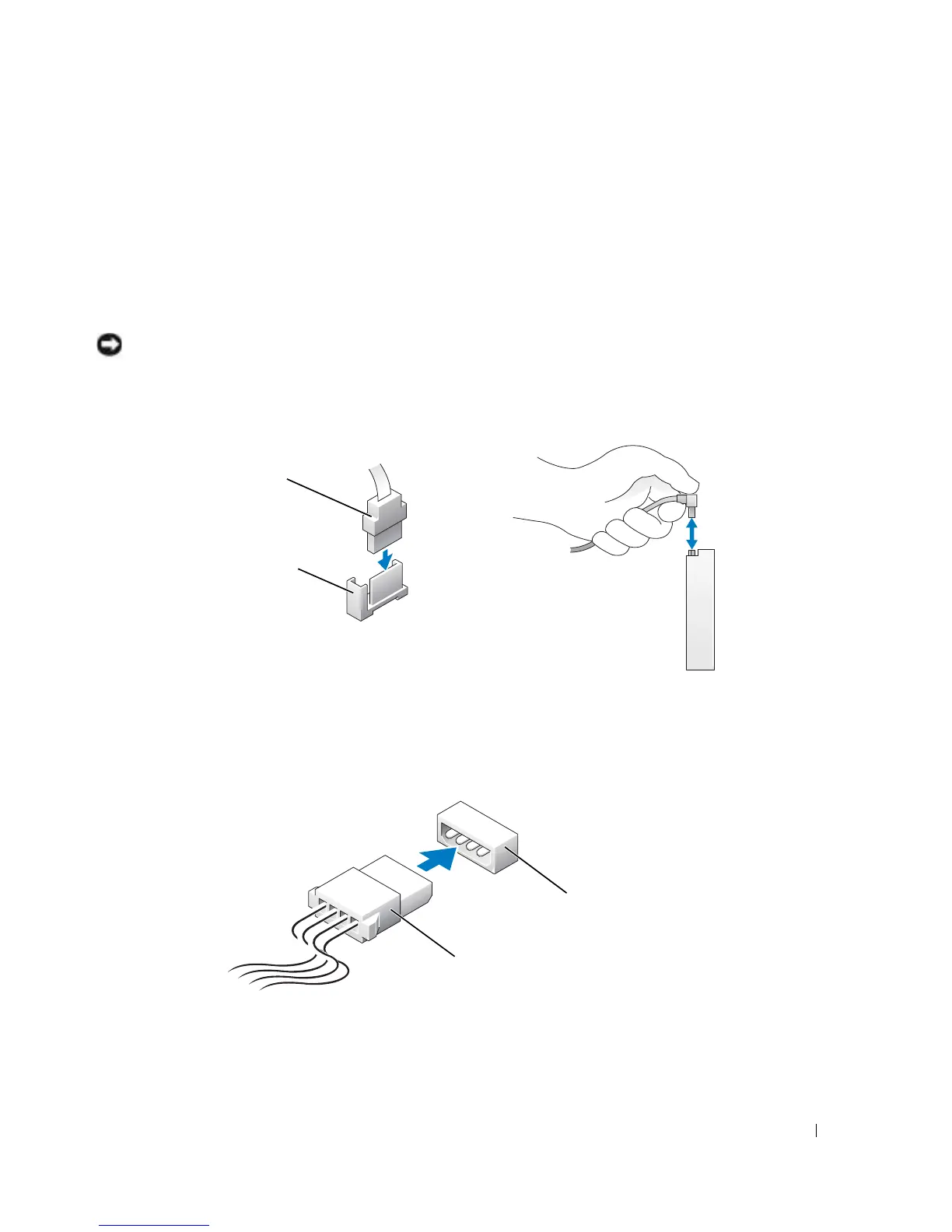
Power Cable Connector
To connect a drive using the power cable, locate the power input connector on the system board.
Serial ATA Connector
interface cable
interface connector
power cable
power input
connector
 Loading...