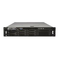
Back-Panel Features and Indicators
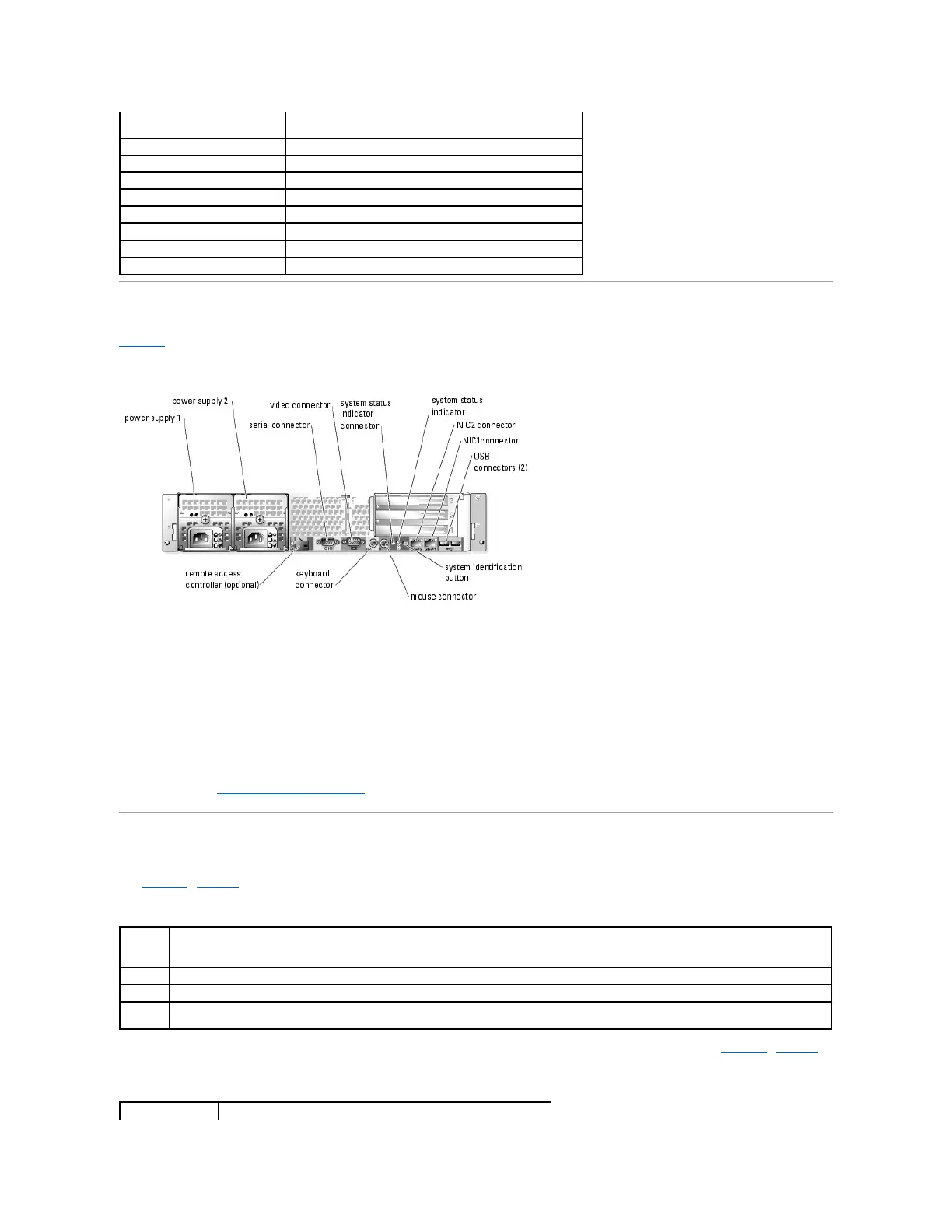
Figure1-3 shows the controls, indicators, and connectors located on the system's back panel.
Figure 1-3. Back-Panel Features and Indicators
Connecting External Devices
When connecting external devices to your system, follow these guidelines:
l Most devices must be connected to a specific connector and device drivers must be installed before the device operates properly. (Device drivers are
normally included with your operating system software or with the device itself.) See the documentation that accompanied the device for specific
installation and configuration instructions.
l Always attach external devices while your system is turned off. Next, turn on any external devices before turning on the system (unless the
documentation for the device specifies otherwise).
For information about individual connectors, see your Installation and Troubleshooting Guide. For information about enabling, disabling, and configuring I/O ports
and connectors, see "Using the System Setup Program."
Power Indicator Codes
The power button on the front panel controls the power input to the system's power supplies. The power indicator can provide information on power status
(see Figure1-4). Table1-4 lists the power button indicator codes.
Table 1-4. Power Button Indicators
The indicators on the optional redundant power supplies show whether power is present or whether a power fault has occurred (see Figure1-4). Table1-5
lists the redundant power supply indicators.
Table 1-5.RedundantPowerSupplyIndicators
 Loading...