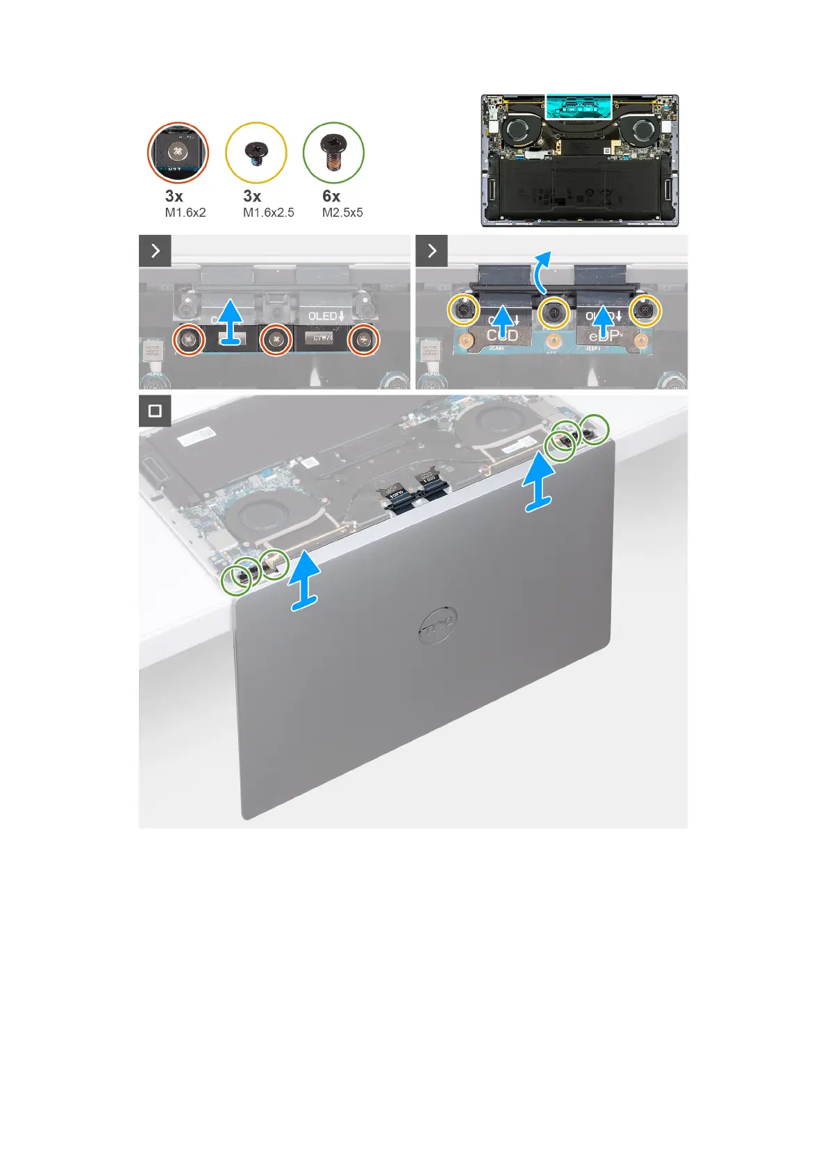
Figure 34. Removing the display assembly
Steps
1. Loosen the three captive screws (M1.6x2) that secure the display-assembly cable bracket to the system board.
2. Lift the display-assembly cable bracket off the system board.
3. Disconnect the camera cable and the display cable from the system board.
4. Remove the three screws (M1.6x2.5) that secure the camera and display-assembly cable holder to the system board.
5. Open the display to a 90-degree angle and place the computer at the edge of a flat table.
6. Remove the three screws (M2.5x5) that secure the left hinge to the system board and the palm-rest and keyboard
assembly.
7. Remove the three screws (M2.5x5) that secure the right hinge to the system board and the palm-rest and keyboard
assembly.
52
Removing and installing Field Replaceable Units (FRUs)
 Loading...