Installing the system board
Prerequisites
If you are replacing a component, remove the existing component before performing the installation process.
About this task
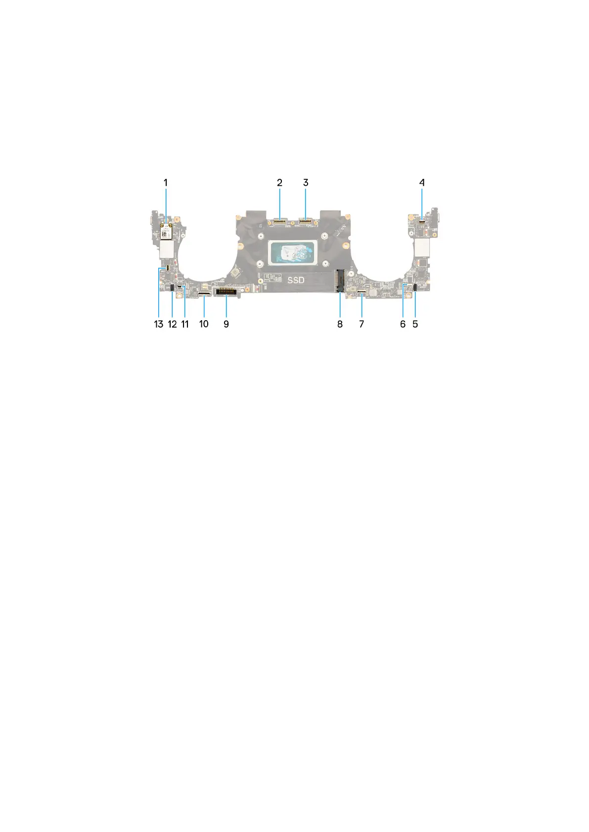
The following image indicates the connectors and components on your system board.
Figure 40. System-board connectors
1.
Wireless card 2. Camera-assembly cable connector
3. Display-assembly cable connector 4. Capacitive touch-panel cable connector
5. Left-speaker cable connector 6. Left-fan cable connector
7. Haptic-module cable connector 8. M.2 solid-state drive slot
9. Battery cable connector 10. Keyboard-daughterboard cable connector
11. Right-fan cable connector 12. Right-speaker cable connector
13. Power-button and fingerprint-reader cable connector
The following images indicate the location of the system board and provide a visual representation of the installation procedure.
Removing and installing Field Replaceable Units (FRUs)
59
 Loading...