- 3 -
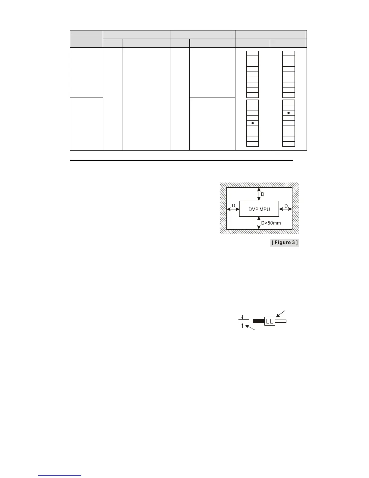
I/O Configuration
Input Output I/O Configuration
Model
Point Type Point Type Relay Transistor
14SS211R Relay
14SS211T
8
DC
(Sink Or Source)
6
Transistor
S/S
X0
X1
X2
X5
X6
X7
Y0
Y1
Y2
Y3
Y4
Y5
X4
C0
C1
X3
S/S
X0
X1
X2
X5
X6
X7
ZP
Y0
Y1
Y4
Y5
X4
UP
Y3
X3
Y2
Note: The layout of output terminals on DVP-SS2 is different from that on DVP-SS.
Dimension & Installation
Please install the PLC in an enclosure with sufficient
space around it to allow heat dissipation, See
[Figure 3].
Direct Mounting: Use M4 screw according to the
dimension of the product.
DIN Rail Mounting: When mounting the PLC to
35mm DIN rail, be sure to use the retaining clip to
stop any side-to-side movement of the PLC and
reduce the chance of wires being loose. The retaining clip is at the bottom of the PLC.
To secure the PLC to DIN rail, pull down the clip, place it onto the rail and gently push
it up. To remove the PLC, pull the retaining clip down with a flat screwdriver and gently
remove the PLC from DIN rail.
Wiring
1. Use 22-16AWG (1.5mm) single or multiple core wire
on I/O wiring terminals. See the figure in the right hand
side for its specification. PLC terminal screws should be
tightened to 1.90 kg-cm (1.65 in-lbs) and please use only
60/75ºC copper conductor.
22-16AWG
< 1.5mm
2. DO NOT wire empty terminal. DO NOT place the I/O signal cable in the same wiring
circuit.
3. DO NOT drop tiny metallic conductor into the PLC while screwing and wiring. Tear
off the sticker on the heat dissipation hole for preventing alien substances from
dropping in to ensure normal heat dissipation of the PLC.
Power Supply
The power input of DVP-SS2 is DC. When operating DVP-SS2, please note the
following points:
1. The power is connected to two terminals, 24VDC and 0V, and the range of power is
20.4 ~ 28.8VDC. If the power voltage is less than 20.4VDC, the PLC will stop running,
all outputs will go “Off”, and the ERROR indicator will start to blink continuously.
2. The power shutdown for less than 10ms will not affect the operation of the PLC.
However, the shutdown time that is too long or the drop of power voltage will stop the
operation of the PLC, and all outputs will go off. When the power returns to normal

 Loading...


