6
ASSEMBLY INSTRUCTIONS
WARNING: FOR YOUR OWN SAFETY, DO NOT CONNECT THE SANDER TO THE POWER SOURCE UNTIL
THE MACHINE IS COMPLETELY ASSEMBLED AND YOU HAVE READ AND UNDERSTOOD THE ENTIRE
OWNERS MANUAL.
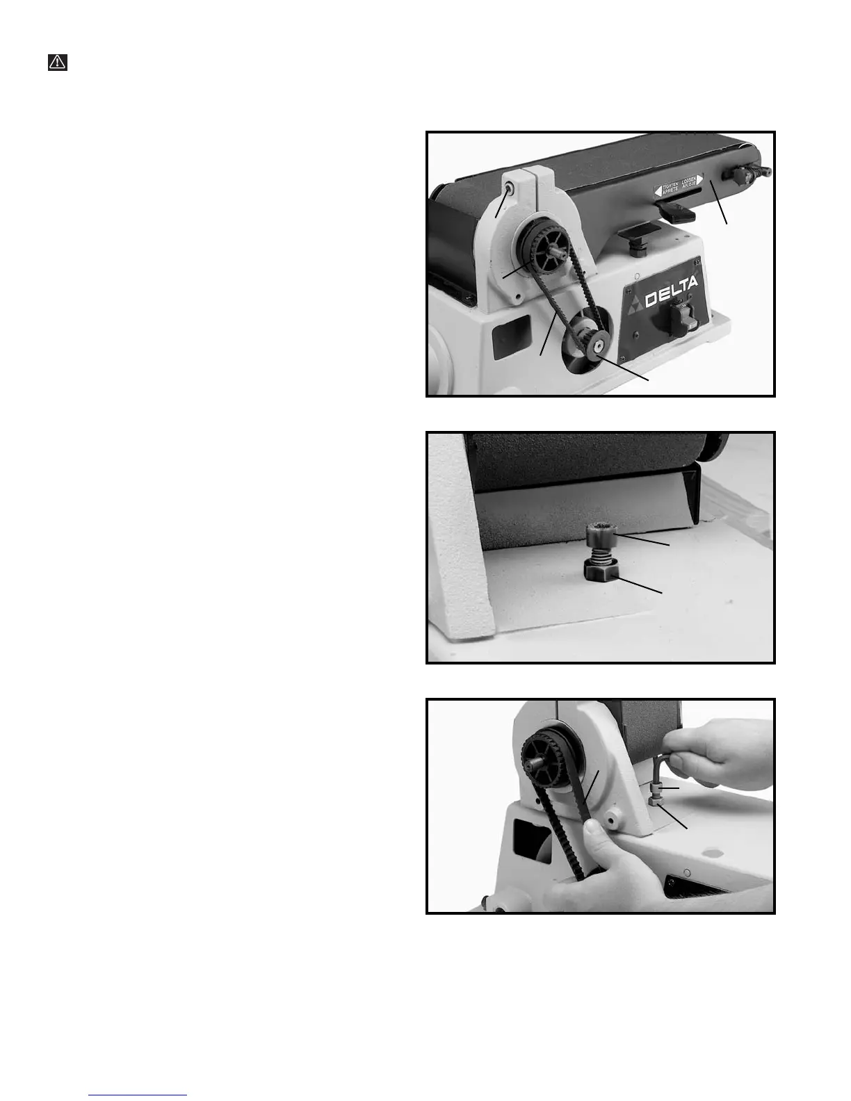
Fig. 2
Fig. 3
Fig. 4
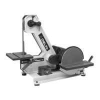
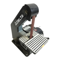
2. Check to see if the belt (A) Fig. 4, is tensioned
properly by applying light pressure to the belt at the
center span of the pulleys as shown. NOTE: THE BELT
(A) SHOULD BE FIRM BUT NOT TOO TIGHT. THE
BELT DOES NOT REQUIRE EXCESSIVE TENSION TO
FUNCTION PROPERLY.
3. If an adjustment is necessary, loosen locknut (G)
Fig. 4, and tighten or loosen adjusting screw (F) until
correct tension is obtained. Then tighten locknut (G).
4. After belt tension is checked and adjusted if neces-
sary, move the sanding arm to the horizontal position.
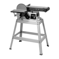
ADJUSTING BELT TENSION
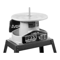
Your sander was shipped from the factory with the drive
belt (A) Fig. 2, assembled to both pulleys (B) and (C).
Before assembling the disc unit to the machine, check
and adjust the belt tension as follows:
1. Loosen screw (D) Fig. 2, and move sanding arm (E)
to the vertical position to expose belt tensioning screw
(F) Fig. 3, and locknut (G).
A
B
C
D
E
F
G
A
F
G
 Loading...