7
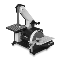
Fig. 8
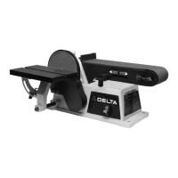
Fig. 6
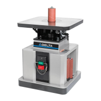
Fig. 7
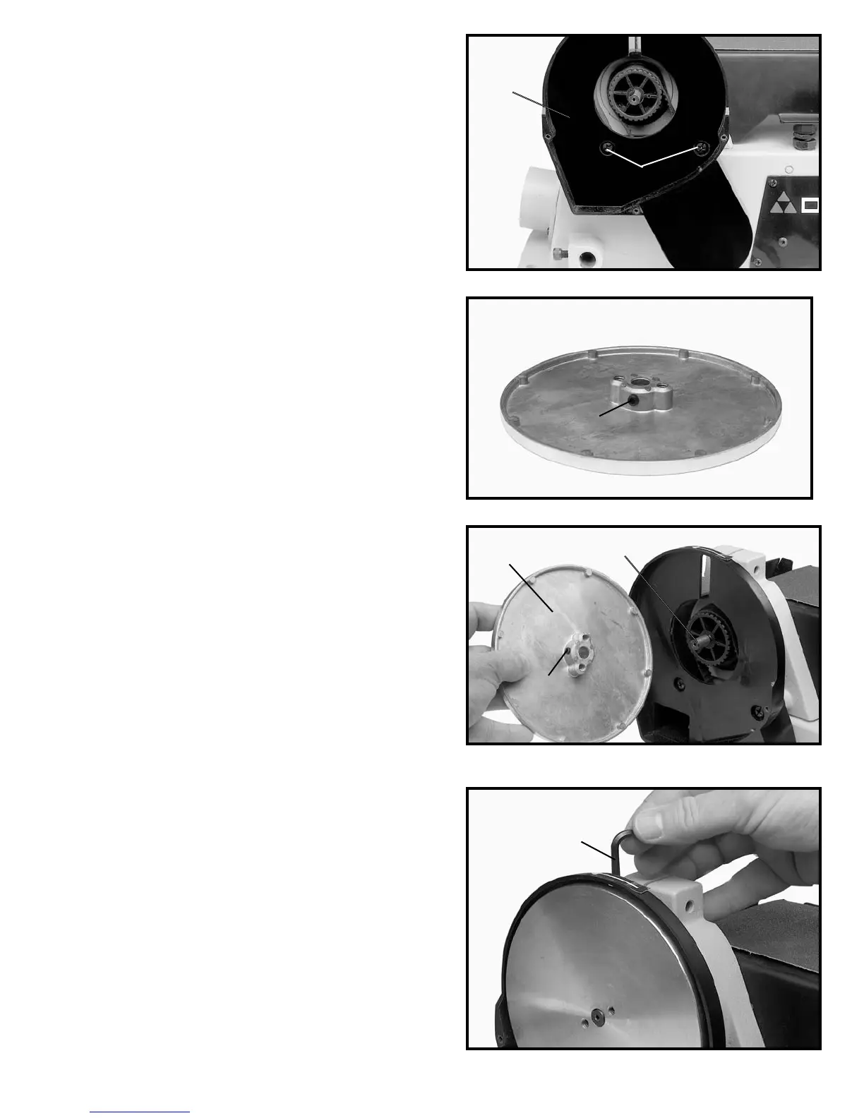
Fig. 5
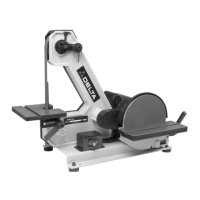
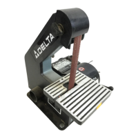
ASSEMBLING BELT
AND PULLEY GUARD
1. Assemble the belt and pulley guard (A) Fig. 5, to the
machine base using the two 1-3/16" (30mm) long screws
(B), as shown.
ASSEMBLING
SANDING DISC PLATE
1. Thread the 1/4" long set screw (A) Fig. 6, into the
tapped hole on hub of sanding disc plate. NOTE: Just
start screw (A) in hole.
2. Slide sanding disc plate (B) Fig. 7, on drive shaft (C)
making sure flat on drive shaft is aligned with set screw
(A) in hub of plate (B). Slide plate (B) onto shaft (C) until
plate surface and shaft are nearly flush. Shaft must not
extend out past surface of plate.
3. Insert hex wrench (D) Fig. 8, down through slot in
the back of belt and pulley guard and tighten set screw
against flat on shaft.
B
A
A
A
B
C
D