13
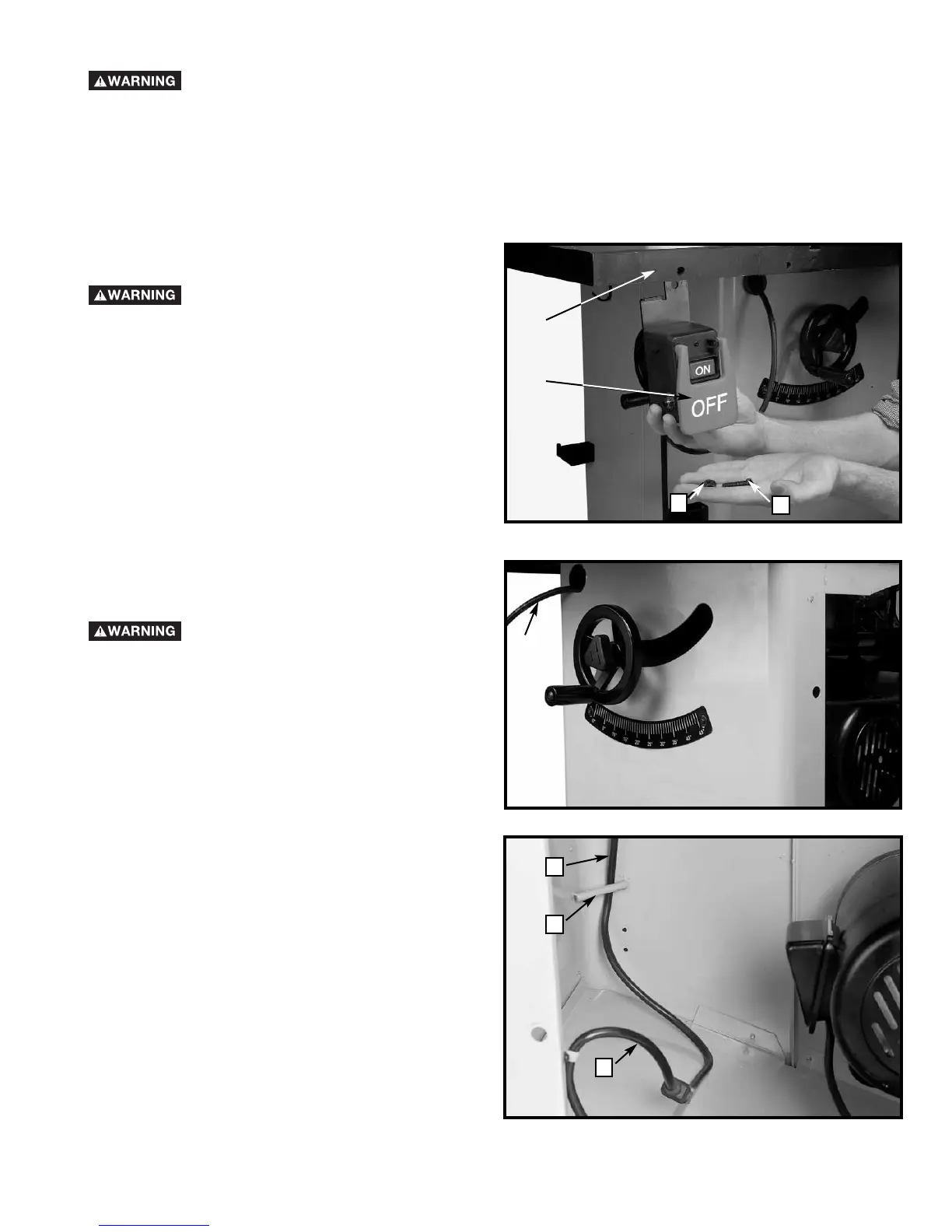
INSTALLING THE SWITCH
DISCONNECT MACHINE FROM POWER
SOURCE.
1. Place switch (A) Fig. 11, behind the lip of extension
wing (B). Insert M8x30 hex head screw (C) through wing
and then switch support. Place an M8 flat washer and
an M8 lock washer on the screw. Thread an M8 hex nut
(D) onto screw and tighten nut securely.
2. Insert switch cord with female end through hole (F)
Fig. 12 in upper left corner of the saw. Open motor
cover and route the switch cord (F) Fig. 13 behind the
cord guard (G) and then plug into motor cord (H), as
shown in Fig. 13.
3. Make sure the slack is pulled down and rests on the
dust chute as shown in Fig. 13.
MAKE SURE CORD DOES NOT COME
IN CONTACT WITH BLADE, BELT OR PULLEYS
Fig. 11
Fig. 12
A
B
C
D
F
H
F
G
Fig. 13
INSTALLING YOUR FENCE SYSTEM
DISCONNECT MACHINE FROM POWER SOURCE.
Assemble the fence system that comes with your saw and follow the instructions included with your fence. Be sure to
locate the M8x25 bolts and M8 washers and lock washers (Nos. 8, 9 and 10 in Fig. 2) which were included in the saw
package. These are used to attach the rear rail to the back of the saw table.
If your fence system does not detail how to mount the switch, follow the instructions below.
For all fence systems, follow steps 2 and 3 below to properly route the cord inside the cabinet.
 Loading...