Chapter 3 Wiring ASDA-M
3-14 Revision December, 2014
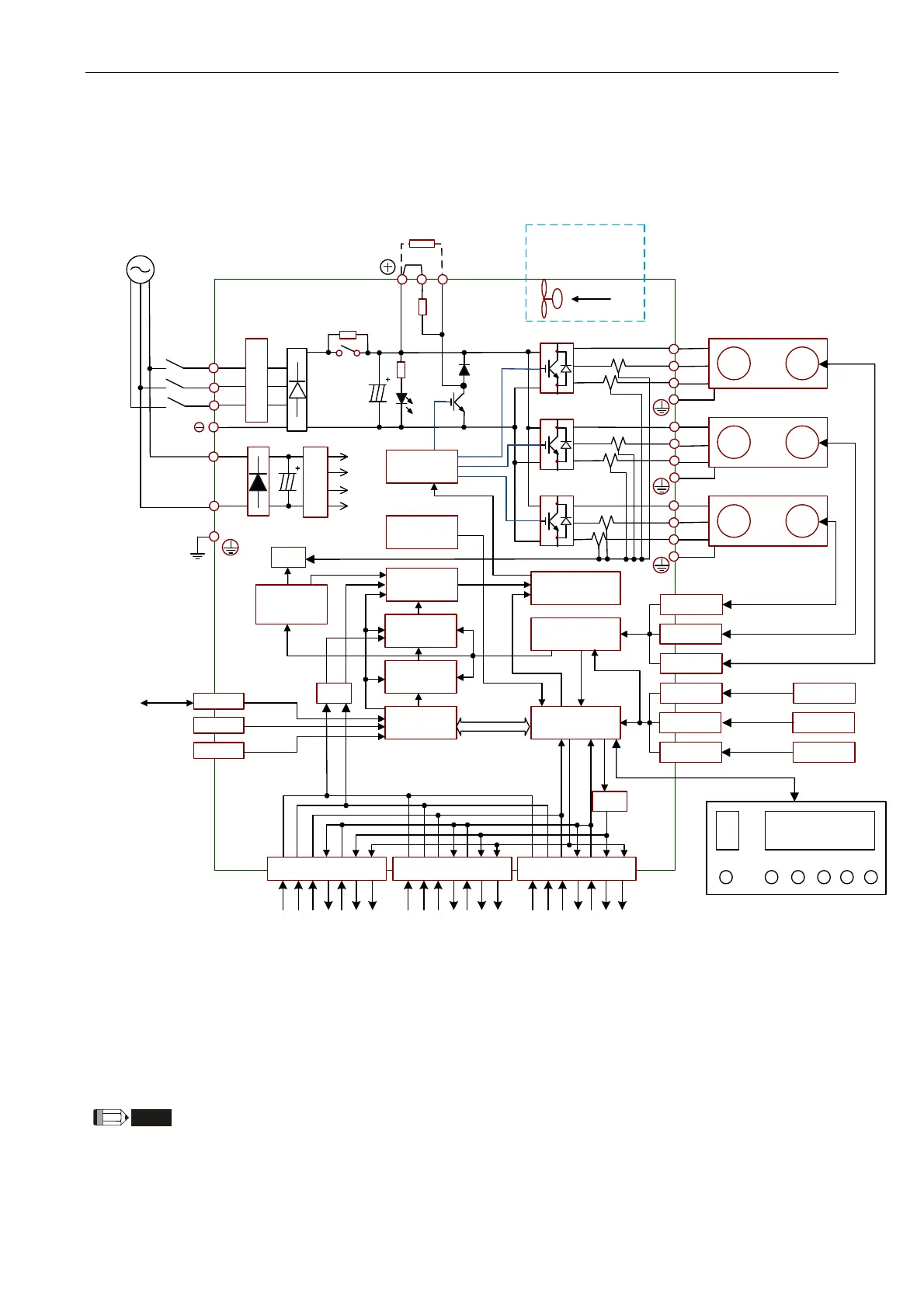
3.2 Schematic Diagram of Servo System
750W~1.5kW Model (Built-in Regenerative Resistor and Fan)
External regenerative
resistor
IGBT_Y
IGBT_Z
U_Y
V_Y
W_Y
Full-closed
loop
Full-closed
loop
Full-closed
loop
Serial
Communication
USB
RS-232/485
IGBT_X
A/D
CPLD
processing
CN5_Z
CN5_Y
CN5_X
CN5_Z
CN5_Y
CN5_X
Encoder signal
processing
CN2_Z
CN2_Y
CN2_X
Encoder
Servo Motor
Encoder
Servo Motor
Encoder
Servo Motor
U_Z
V_Z
W_Z
U_X
V_X
W_X
PWM Output
Current
Control
Speed Control
Position
Control
DSP
operation
Data Bus
Current signal
processing
A/D
Protect
circuit
CN6
CN3
CN4
GATE
DRIVER
Motor
Encoder
Motor
Encoder
Motor
Encoder
Rectifying
circuit
Regeneration
Circuit
N
P
Control
Power
±15V
5V
18V
24V
Lack phase
detection
R
S
T
L1c
L2c
Operation
Display
MODE
SHIFT
SET
SEL
UP DOWN
D
P
C
Power
750W、1.5kW single/three-phase 200~230V
1.5 one group of fan
A/D
CN1_X
Ext ernal speed
External torque
Position pulse
Digital output
Digital input
Analog output
A, B, Z Output
Ext ernal speed
External torque
Position pulse
Digital output
Digital Input
Analog output
A, B, Z Output
CN1_Y
Ext ernal speed
External torque
Position pulse
Digital output
Digital input
Analog output
A,B,Z Output
CN1_Z
750W one group of fan
12V
NOTE
1) The extension socket CN6 of ASD-M-0721-M model and ASD-M-1521-M is the function of
CANopen.
2) The extension socket CN6 of ASD-M-0721-F model and ASD-M-1521-F is the function of
DMCNET.
3) ASD-M-0721-L model and ASD-M-1521-L model have no extension socket CN6.
 Loading...