10
ADJUSTING SPINDLE
ASSEMBLY
If excessive play develops in the spindle assembly, or if
noise level increases after extended use, make the fol-
lowing adjustment to the spindle assembly.
1. DISCONNECT MACHINE FROM POWER SOURCE.
2. Turn the machine over and place it on a firm
supporting surface. Be careful not to damage the
spindle assembly.
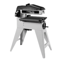
3. Remove the four mounting screws (A) Fig. 22 and
remove the case (B) from the machine.
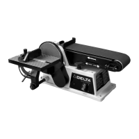
4. IMPORTANT: Shaft (C) Fig. 23, must be positioned
inside the center of bracket (D). To adjust, loosen the
two locknuts (E) Fig. 23. Tighten or loosen the two
adjusting screws (F) as necessary until the shaft (C) is
centered inside the bracket (D), with the adjustment
screws (F) contacting the shaft. Tighten the two locknuts
(E) Fig. 23.
5. Attach the case with the four screws removed in
STEP 3.
Fig. 22
A
A
Fig. 23
B
E
F
F
C
D
OPERATION
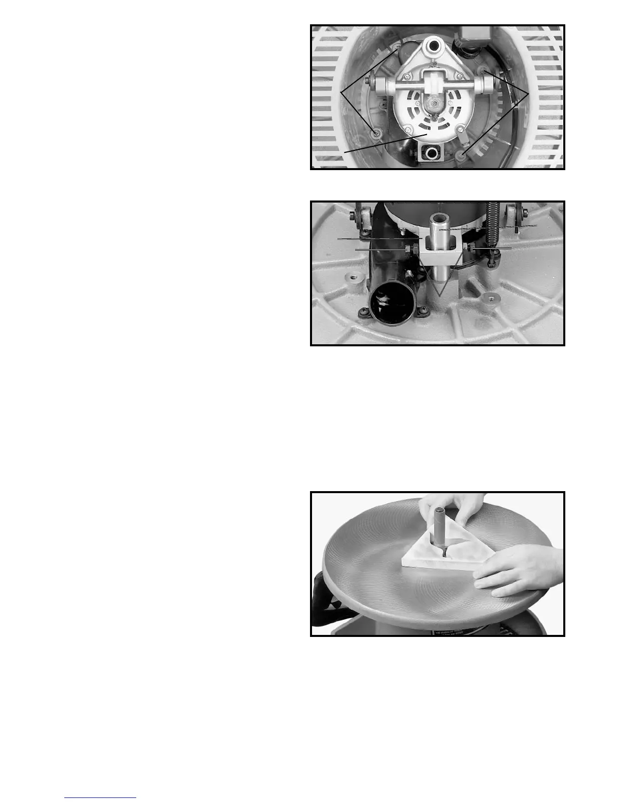
Fig. 24, illustrates sanding inside curves.
IMPORTANT: Always sand against the rotation of the
sanding drum.
The oscillating action of the sanding drum minimizes
score marks and prevents clogging of the sanding drum,
providing faster, smoother sanding and increasing the
life of the sanding sleeve.
Fig. 24
 Loading...