9
OPERATING CONTROLS AND ADJUSTMENTS
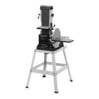
STARTING AND STOPPING
SANDER
The on/off switch (A) Fig. 18, is located on the sander
base. To turn the sander “ON”, move the switch up to
the “ON” position. To turn the sander “OFF”, move the
switch down to the “OFF” position.
Fig. 18
A
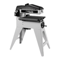
LOCKING SWITCH IN THE
“OFF” POSITION
IMPORTANT: When the machine is not in use, the
switch should be locked in the “OFF” position to prevent
unauthorized use. This can be done by grasping the
switch toggle (A) and pulling it out of the switch, as
shown in Fig. 19. With the switch toggle (A) removed, the
switch will not operate. However, should the switch
toggle be removed while the sander is running, it can be
turned “OFF” once, but cannot be restarted without
inserting the switch toggle (A).
Fig. 19
B
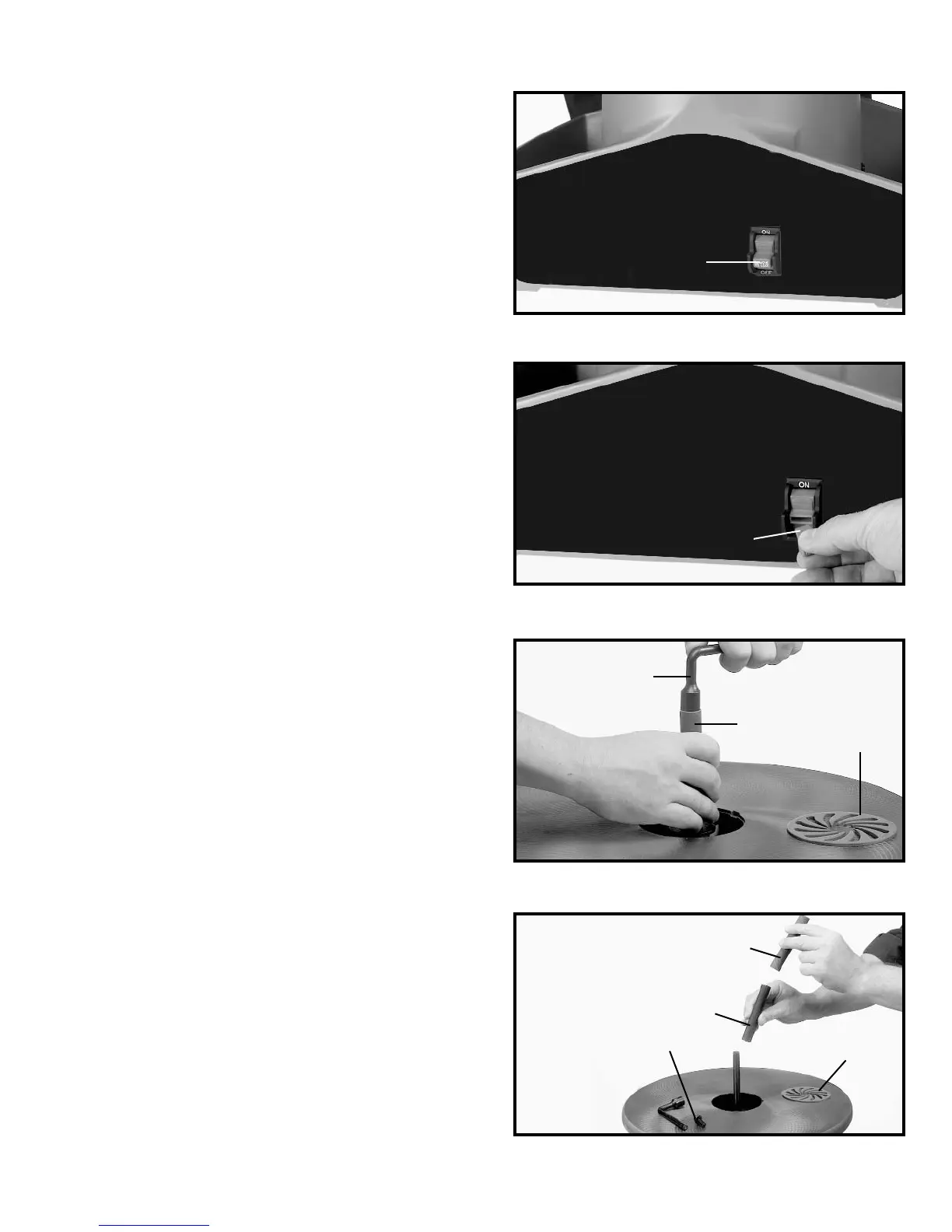
CHANGING ABRASIVE
SLEEVES AND SANDING
DRUMS
1. DISCONNECT MACHINE FROM POWER SOURCE.
2. Remove table insert (A) Fig. 20.
3. Use the supplied socket wrench (B) Fig. 20, to
remove the arbor screw, turn screw clockwise. Remove
the abrasive sleeve (C) with the sanding drum from the
spindle assembly.
4. Slide the used abrasive sleeve off the sanding drum.
Slide the new abrasive sleeve (C) Fig. 21, on sanding
drum (D).
5. Place the abrasive sleeve and sanding drum
combination (C) Fig. 20, firmly on the spindle adapter,
and replace the arbor screw (E) Fig. 21. Tighten the
arbor screw (E) Fig. 21 with socket wrench (B) Fig. 20, by
turning nut counter-clockwise. Replace the table insert
(A) Fig. 21, with the arrows up.
Fig. 20
Fig. 21
A
B
C
C
D
E
A
 Loading...